Custom Plasma Cutting Service
Experience precision and quality like never before with our custom plasma cutting service. We use the latest technology to ensure the highest level of accuracy and consistency.
Send us your designs and specifications for a free quotation
All uploaded files are secure and confidential
What Is Plasma Cutting Service
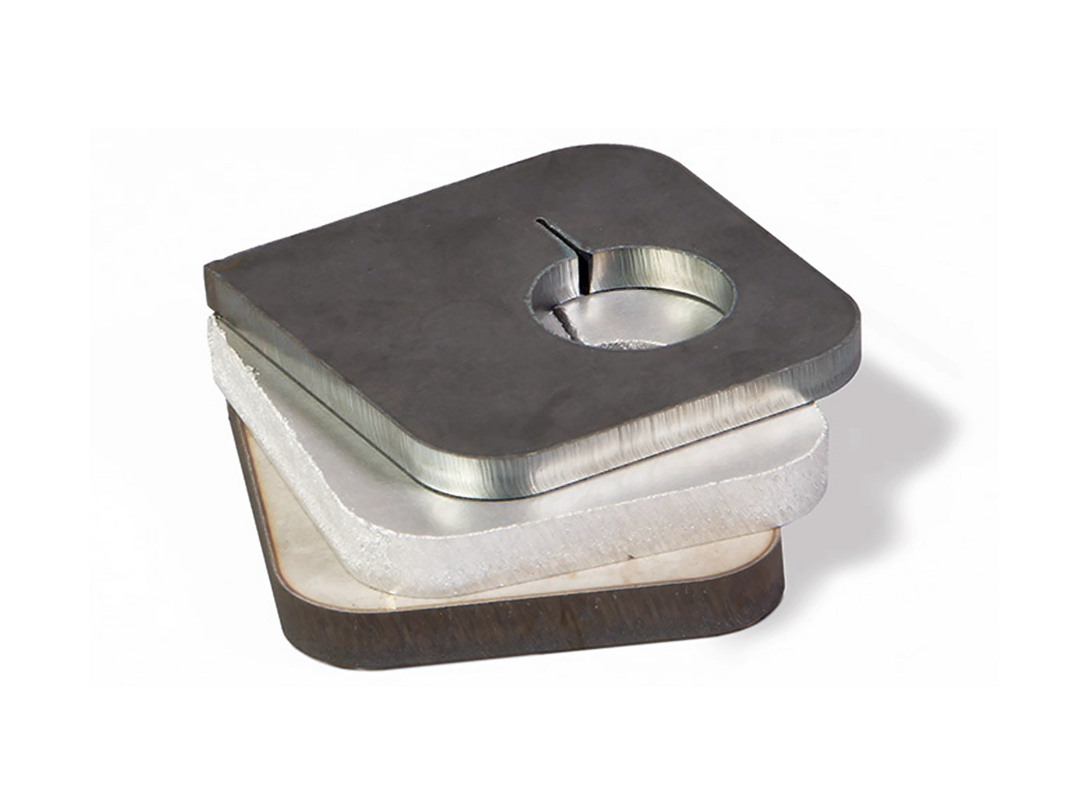
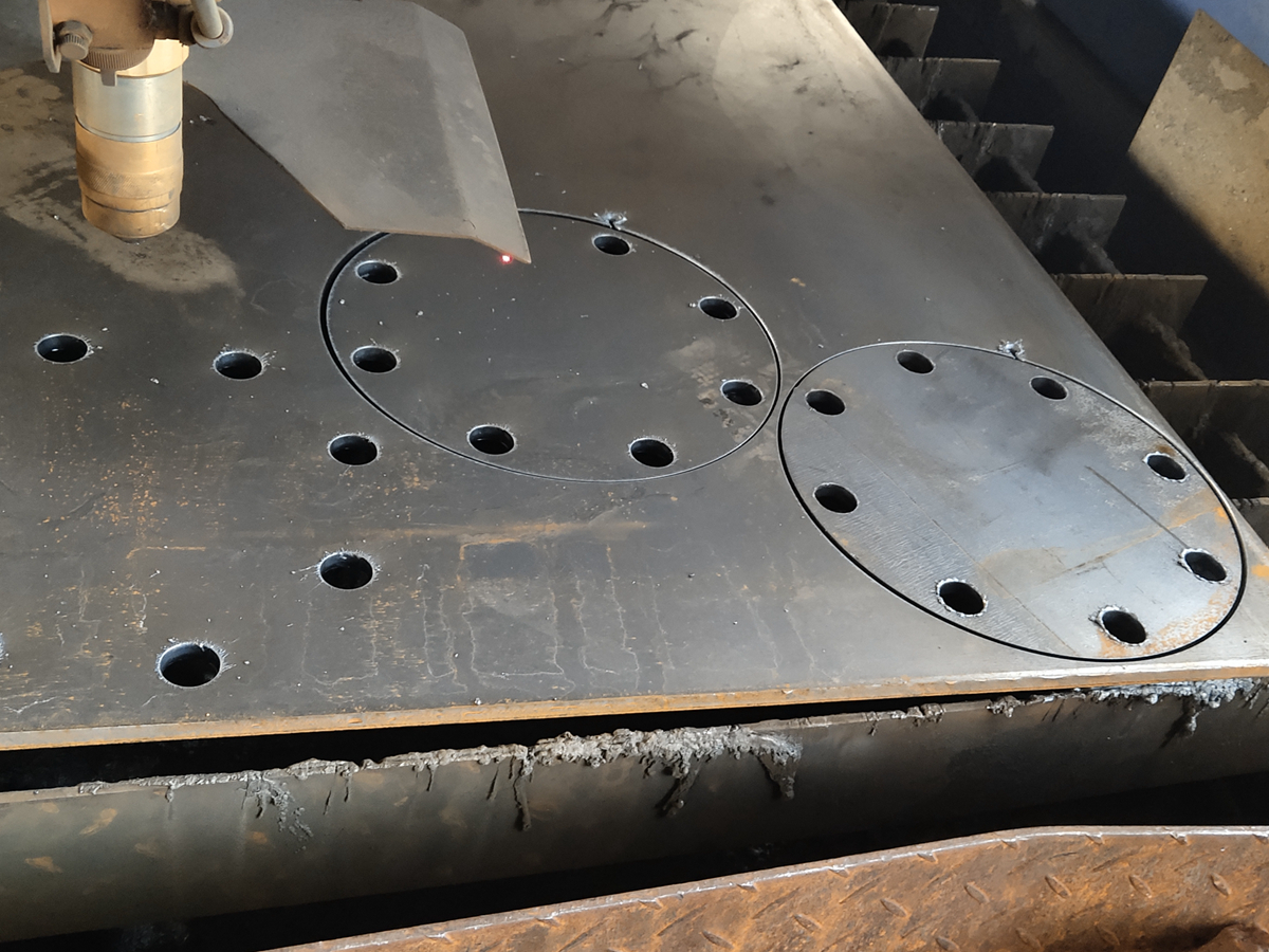
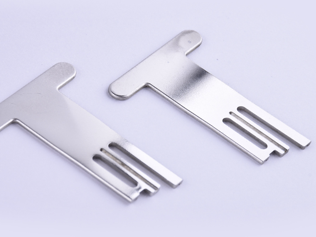
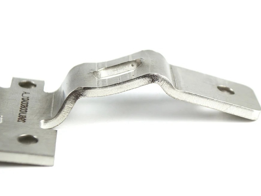
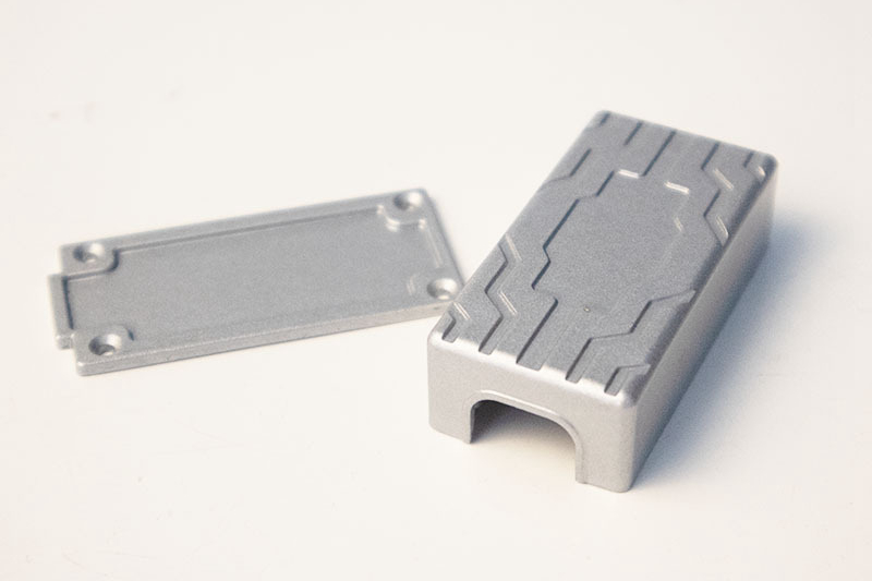
Our Plasma Cutting Service delivers high-speed, high-precision cutting for a wide range of metals. Using advanced plasma technology, we achieve superior cut quality, minimal kerf loss, and high production throughput for various industrial applications.
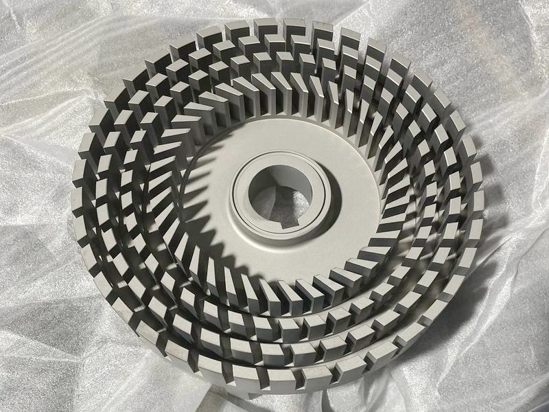
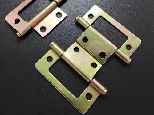
Applications of Plasma Cutting Parts
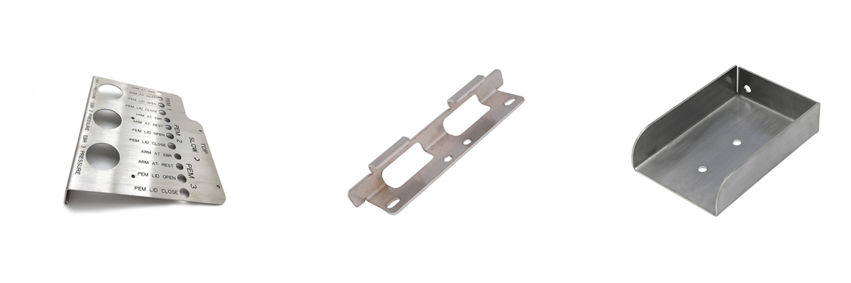
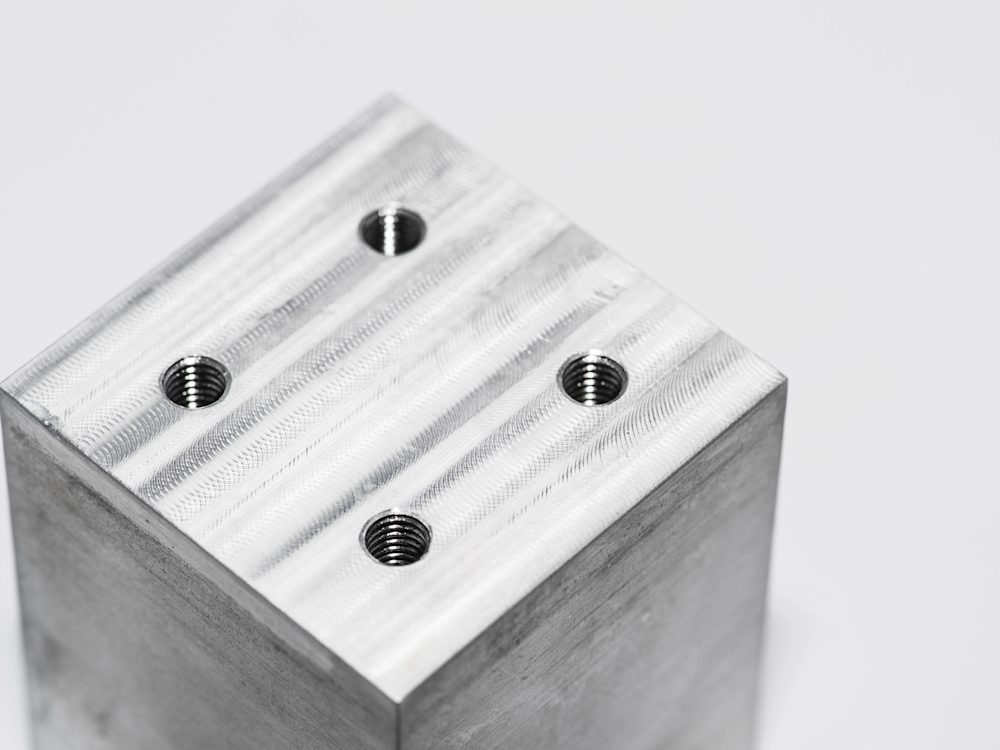
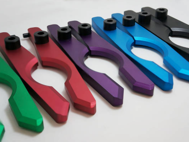
Our plasma cutting process delivers precision and versatility for producing custom metal parts. Explore high-quality, tailored components for a wide range of industrial applications.
Neway Plasma Cutting Service Capabilities
Get Precision and Quality with Our Custom Plasma Cutting Services! We are a leading manufacturer of custom plasma-cut parts. With state-of-the-art equipment and experienced technicians, we deliver precise and accurate cuts for a wide range of materials. Trust us for all your plasma cutting needs!
Custom Parts Surface Finishing Available
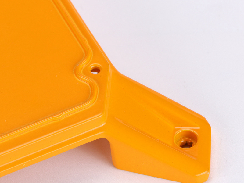
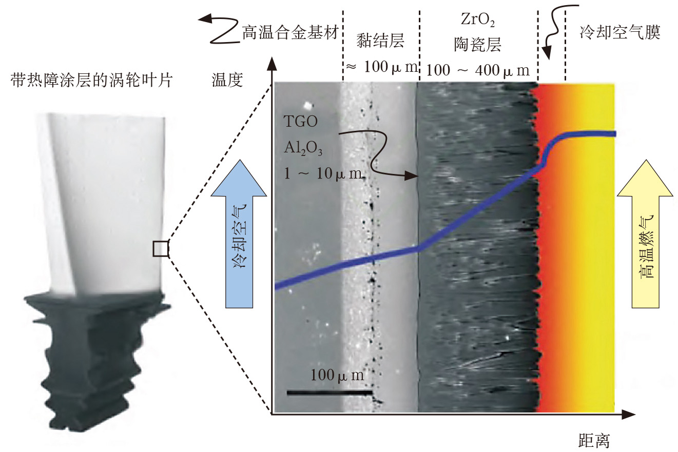
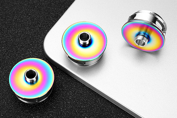
Our Surface Treatment Service offers specialized finishes for custom parts, enhancing durability, aesthetics, and performance. We provide a range of processes, including Electroplating, Anodizing, Powder Coating, and Thermal Barrier Coatings, tailored to improve corrosion resistance, wear properties, and visual appeal of metal and plastic components across industries.
learn more
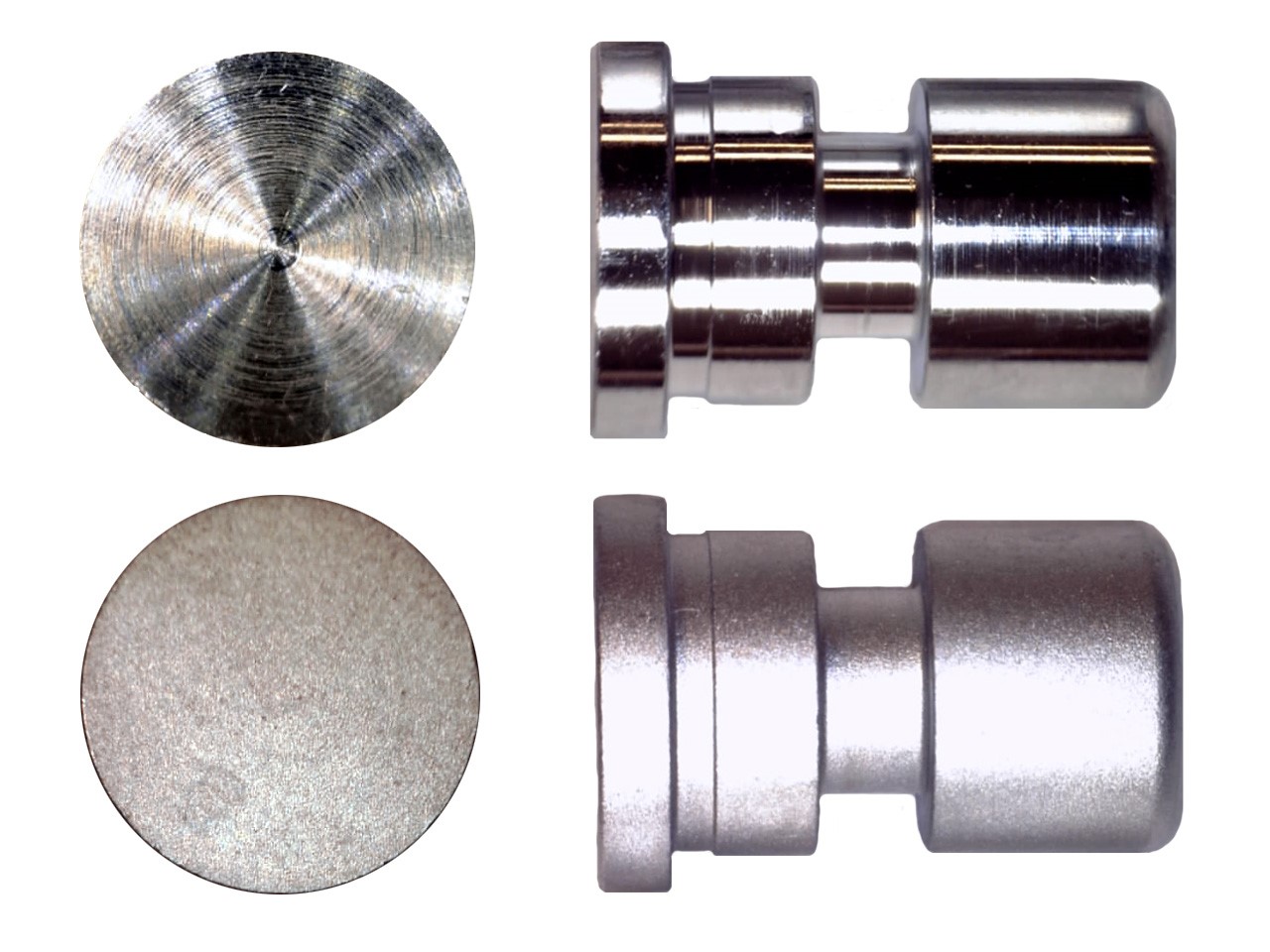
As Machined
learn more
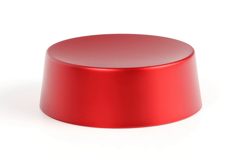
Painting

learn more
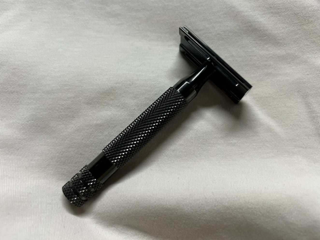
PVD
learn more
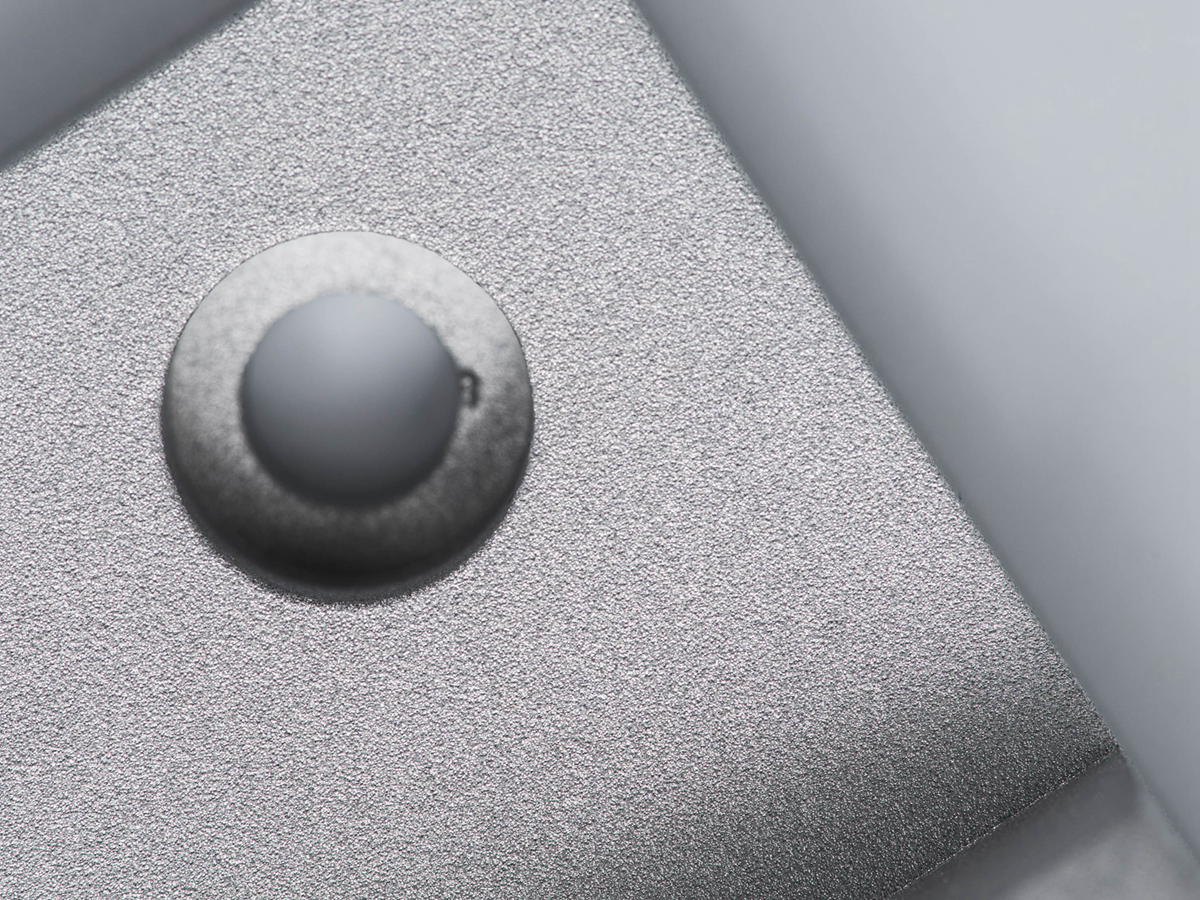
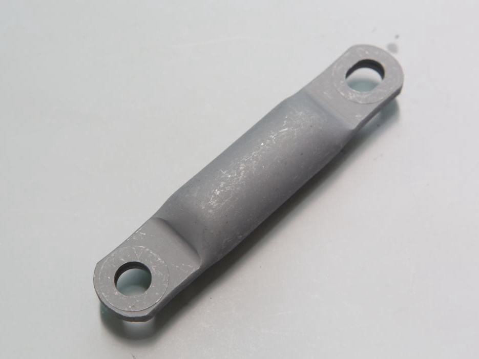
Sandblasting
learn more
Electroplating
learn more
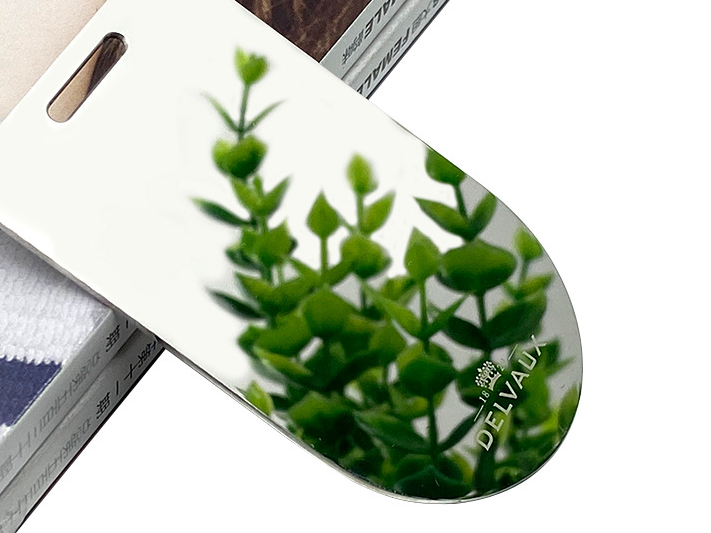
Polishing
learn more
Anodizing
learn more
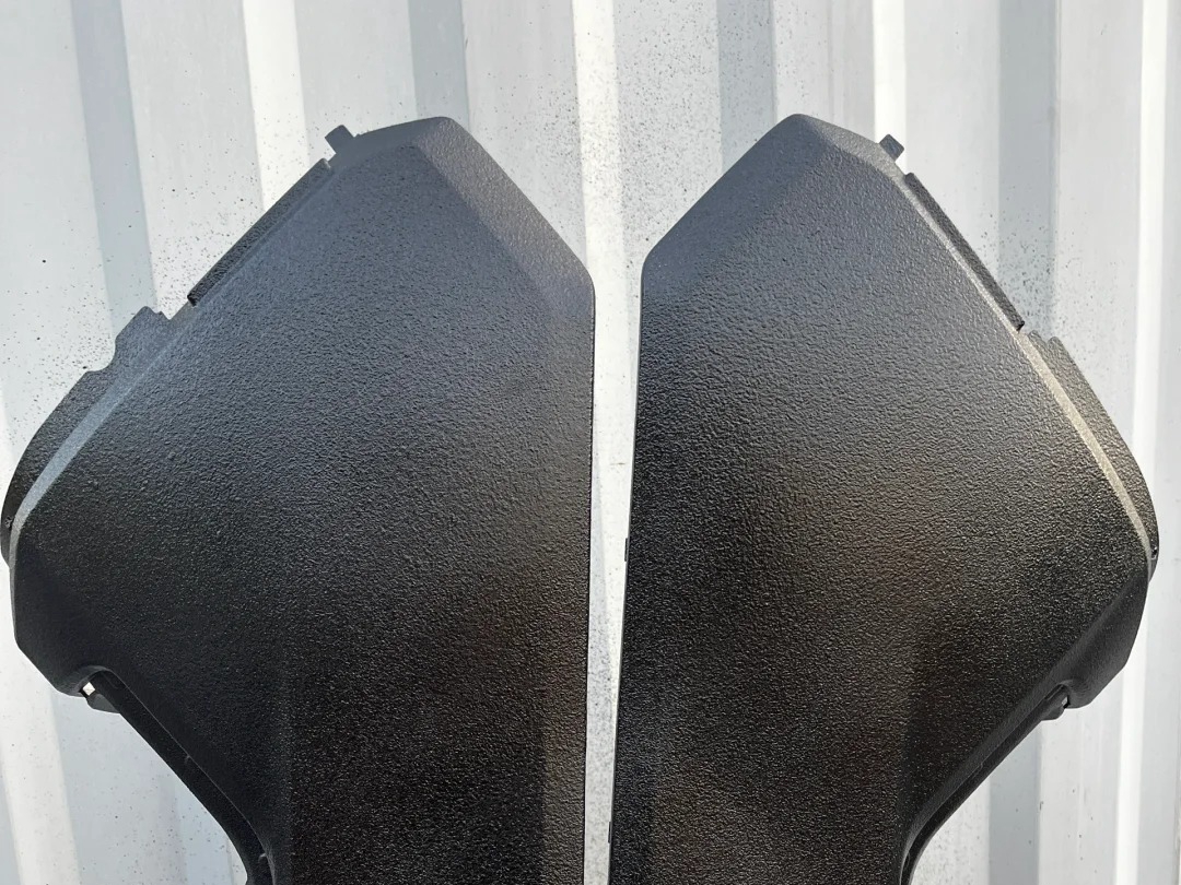
Powder Coating
learn more
Electropolishing
learn more
IMD
learn more
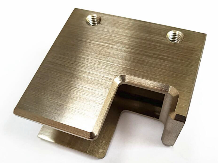
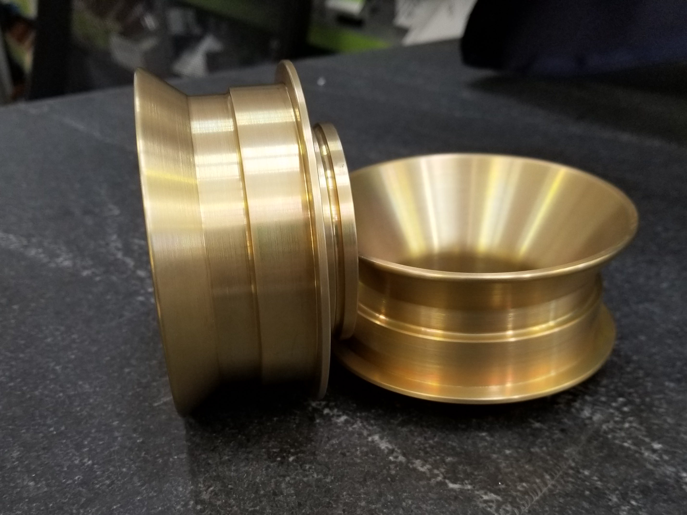
Brushed Finishes
learn more
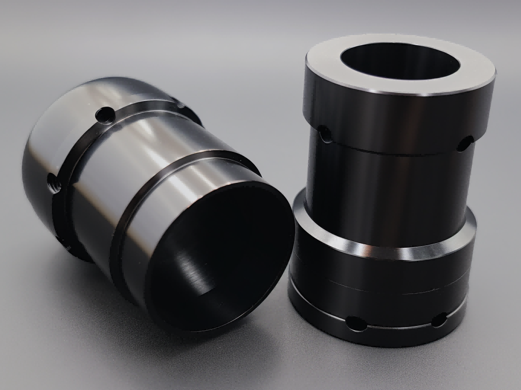
Black Oxide
learn more
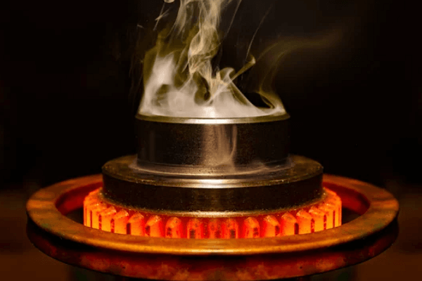
Heat Treatment
learn more
Tumbling
learn more
Alodine
learn more
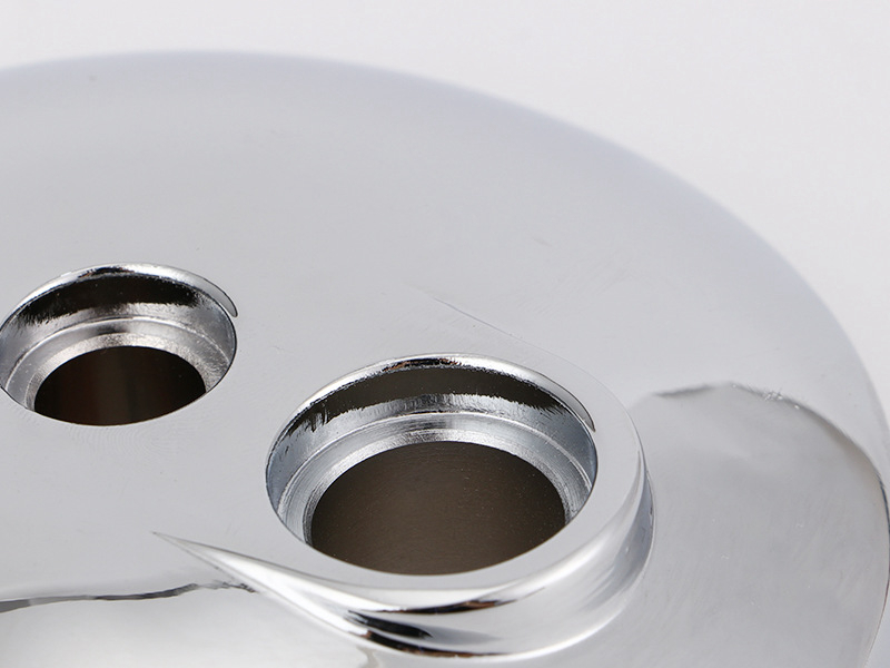
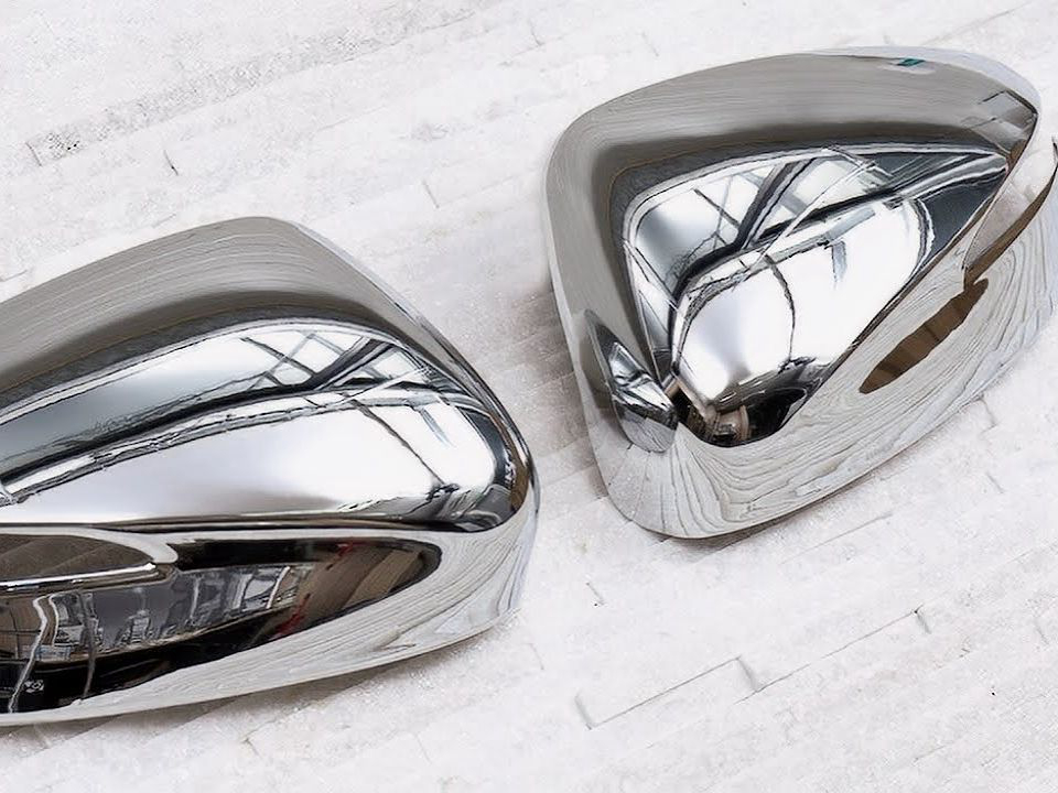
Chrome Plating
learn more
Phosphating
learn more
Nitriding
learn more
Galvanizing
learn more
Lacquer Coating
learn more
Teflon Coating
learn more
Thermal Coatings
learn more
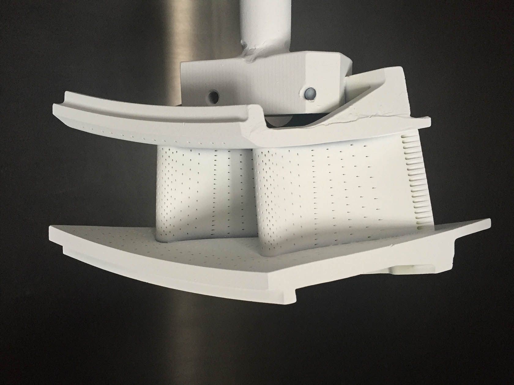
Thermal Barrier Coatings
learn more
Passivation
Let's Start A New Project Today
Custom Plasma Cutting Parts Design Guideline
These guidelines provide industry standard values for custom plasma cutting parts to ensure precise cutting, reduced thermal distortion, and optimal structural integrity, ultimately improving efficiency and quality while lowering production costs.
Frequently Asked Questions
Explore Related Resources
Neway Precision Works Ltd.
No.3 Lefushan Industry West Road
Fenggang, Dongguan, China
ZIP 523000
Solutions
Copyright © 2025 Neway Precision Works Ltd.All Rights Reserved.