Metal Bending Service
Efficient and Cost-effective Metal Bending Services! Need metal bending done right and on time? Look no further. Our experienced team and advanced equipment ensure quick turnaround times and competitive pricing. Contact us for a quote and let us exceed your expectations
Send us your designs and specifications for a free quotation
All uploaded files are secure and confidential
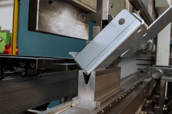
What Is Metal Bending Service
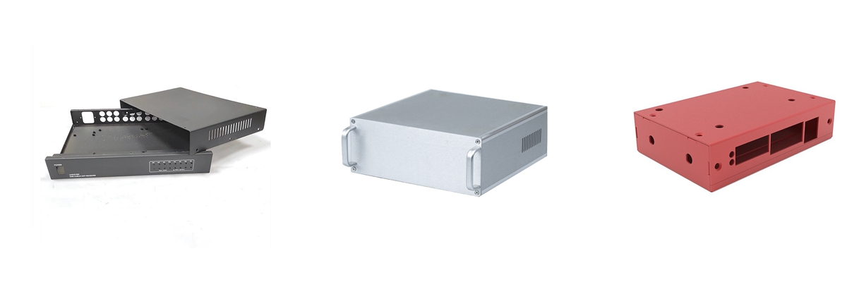
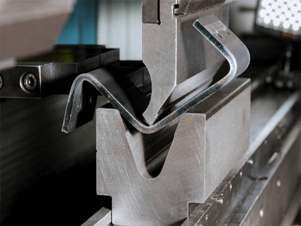
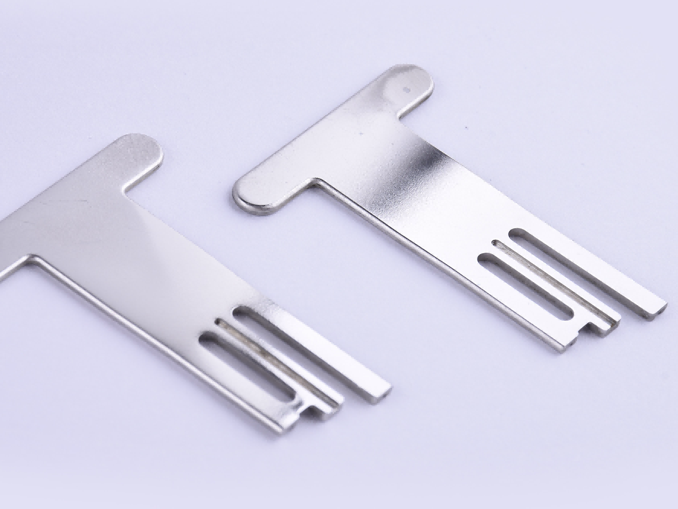
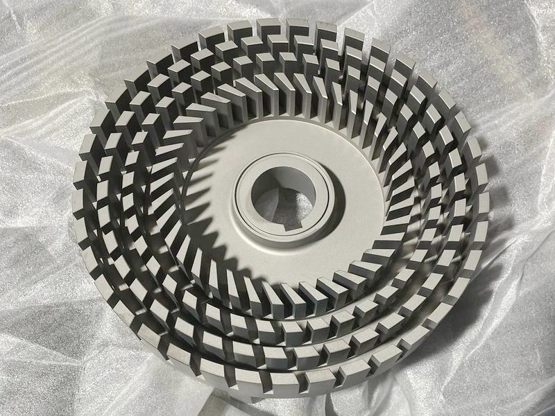
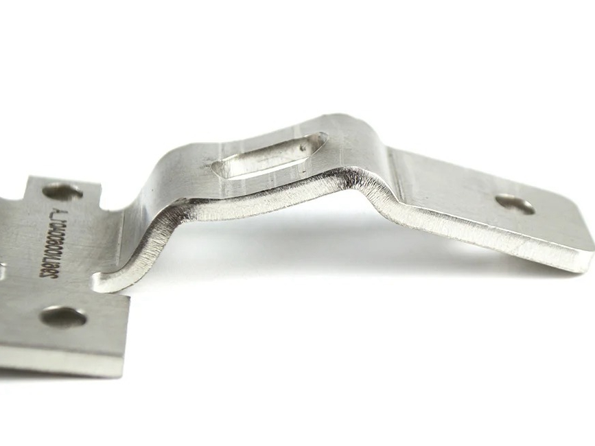
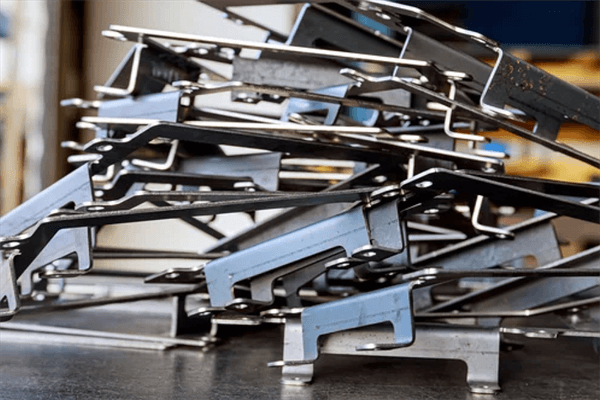
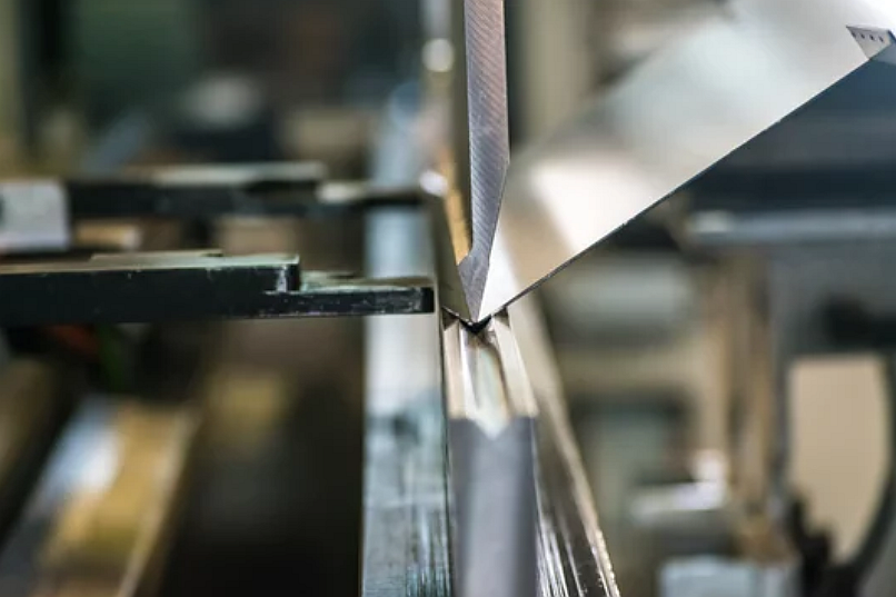
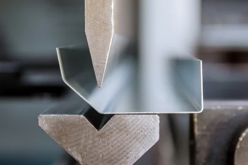
Our Metal Bending Service provides high-precision bending solutions to transform flat metal sheets into complex shapes. Our advanced technology ensures consistent bends, efficient production, and minimal material waste, meeting diverse industrial requirements.
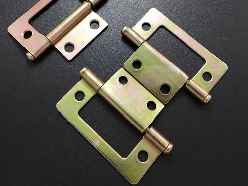
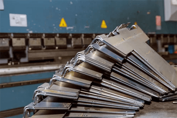
Applications of Metal Bending Parts
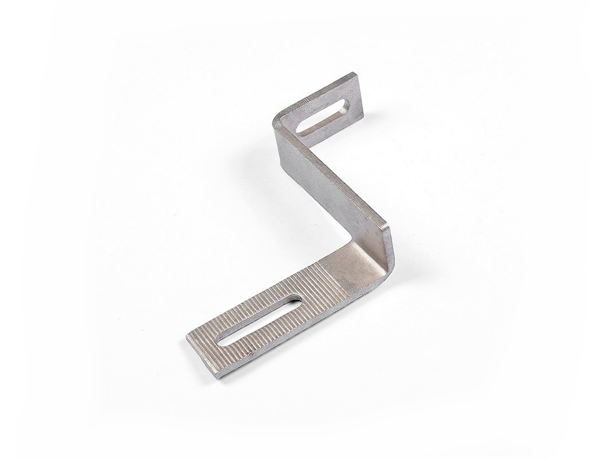
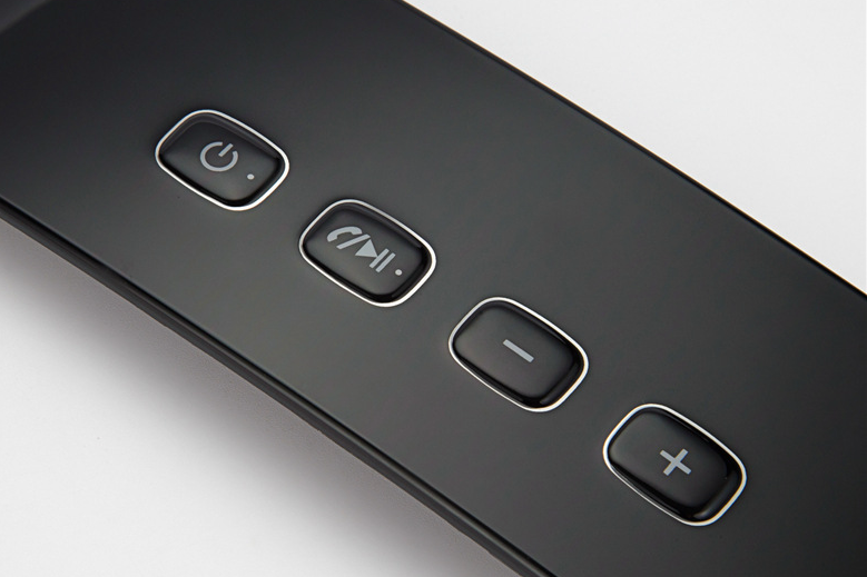
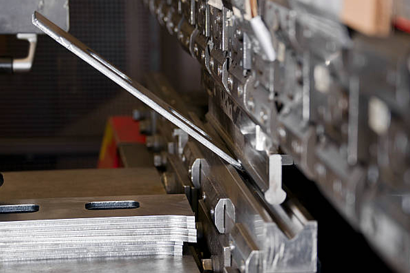
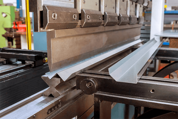
Our metal bending process provides high precision and durable components essential for various industries. Explore the wide range of applications from aerospace to locking systems.
Neway Custom Plasma Cutting Capabilities
Need custom metal bending services at an affordable price? Neway has got you covered! Our competitive pricing ensures that you receive excellent value for your investment, without compromising on quality. With a wide range of metal bending capabilities and exceptional customer service, we work closely with you to understand your unique requirements and provide customized solutions that meet your specific needs. Contact us today to get started!
Custom Parts Surface Finishing Available
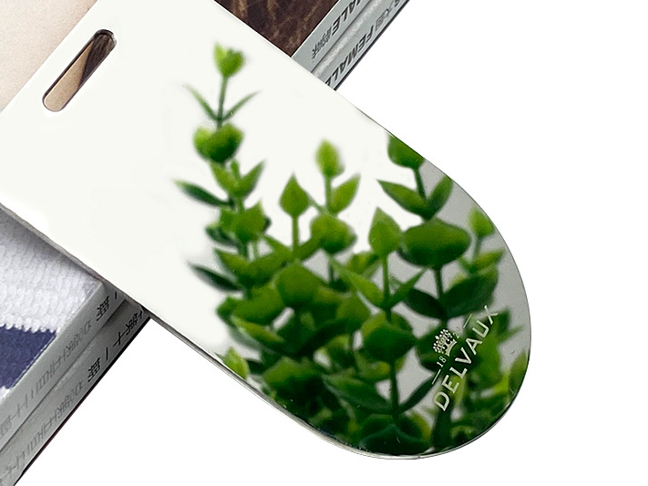
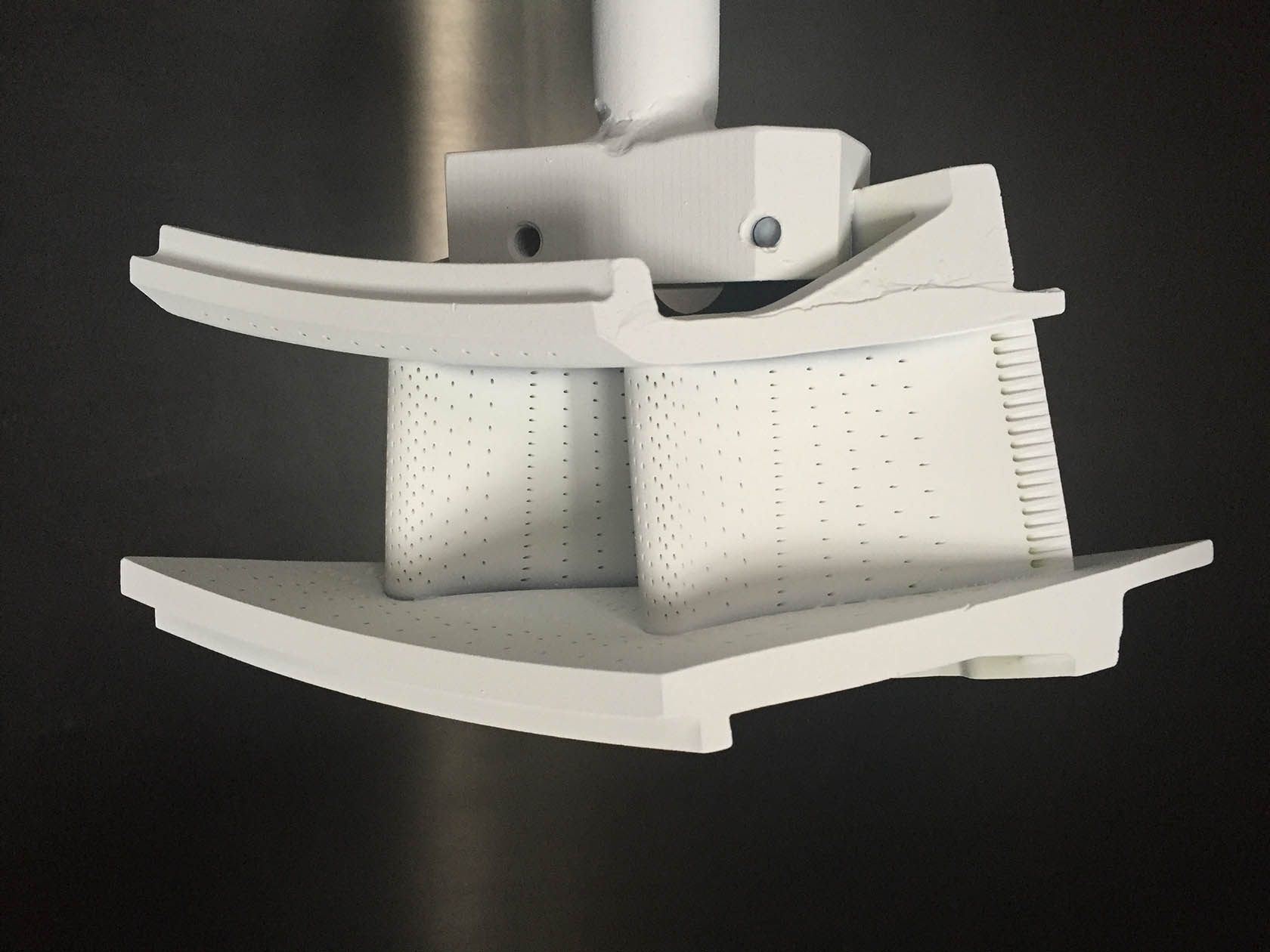
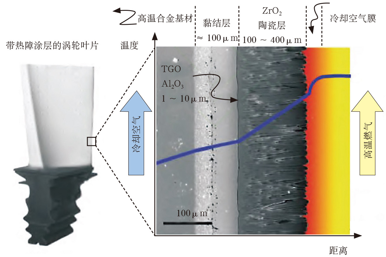
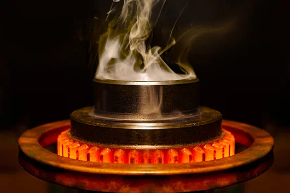
Our Surface Treatment Service offers specialized finishes for custom parts, enhancing durability, aesthetics, and performance. We provide a range of processes, including Electroplating, Anodizing, Powder Coating, and Thermal Barrier Coatings, tailored to improve corrosion resistance, wear properties, and visual appeal of metal and plastic components across industries.
learn more
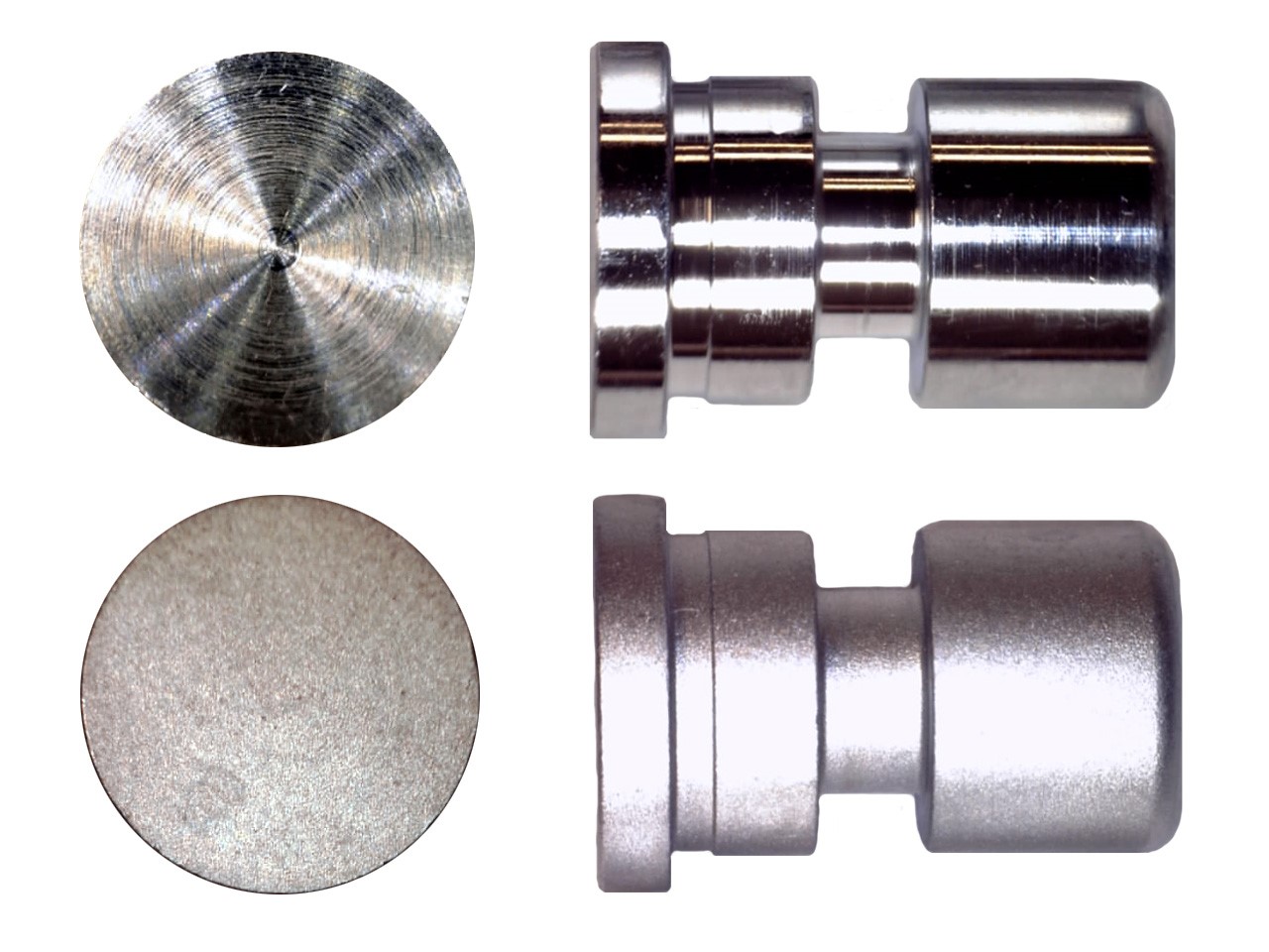
As Machined
learn more
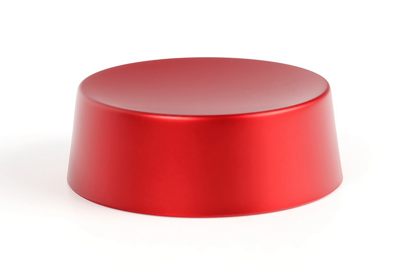
Painting
learn more
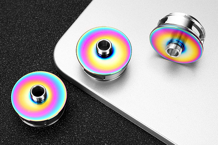
PVD
learn more
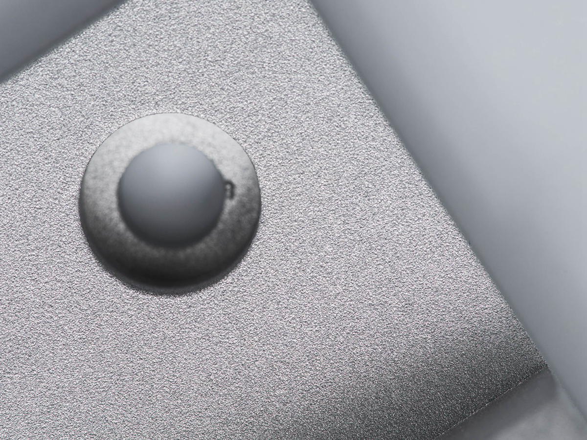
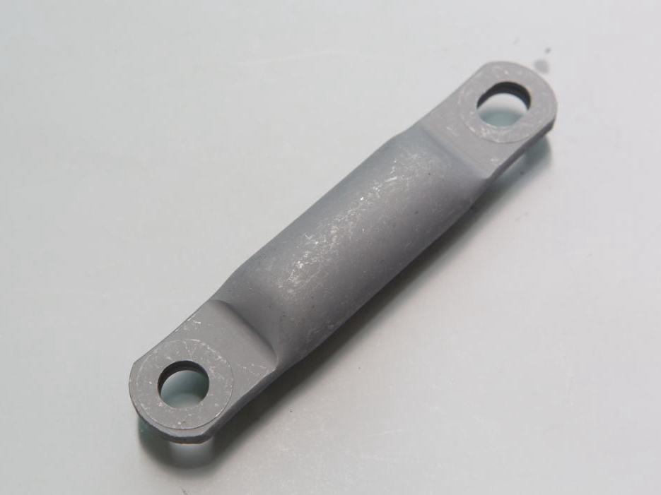
Sandblasting
learn more
Electroplating
learn more
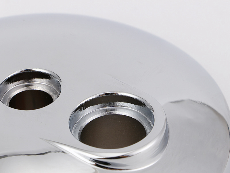
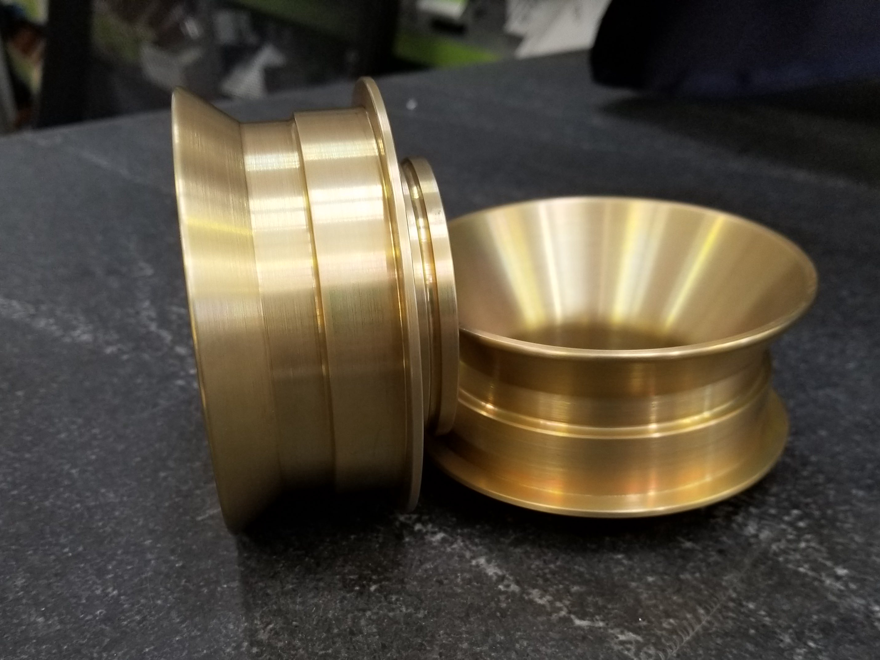
Polishing
learn more
Anodizing
learn more
Powder Coating
learn more
Electropolishing
learn more
IMD
learn more
Brushed Finishes
learn more
Black Oxide
learn more
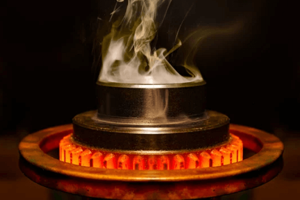
Heat Treatment
learn more
Tumbling
learn more
Alodine
learn more
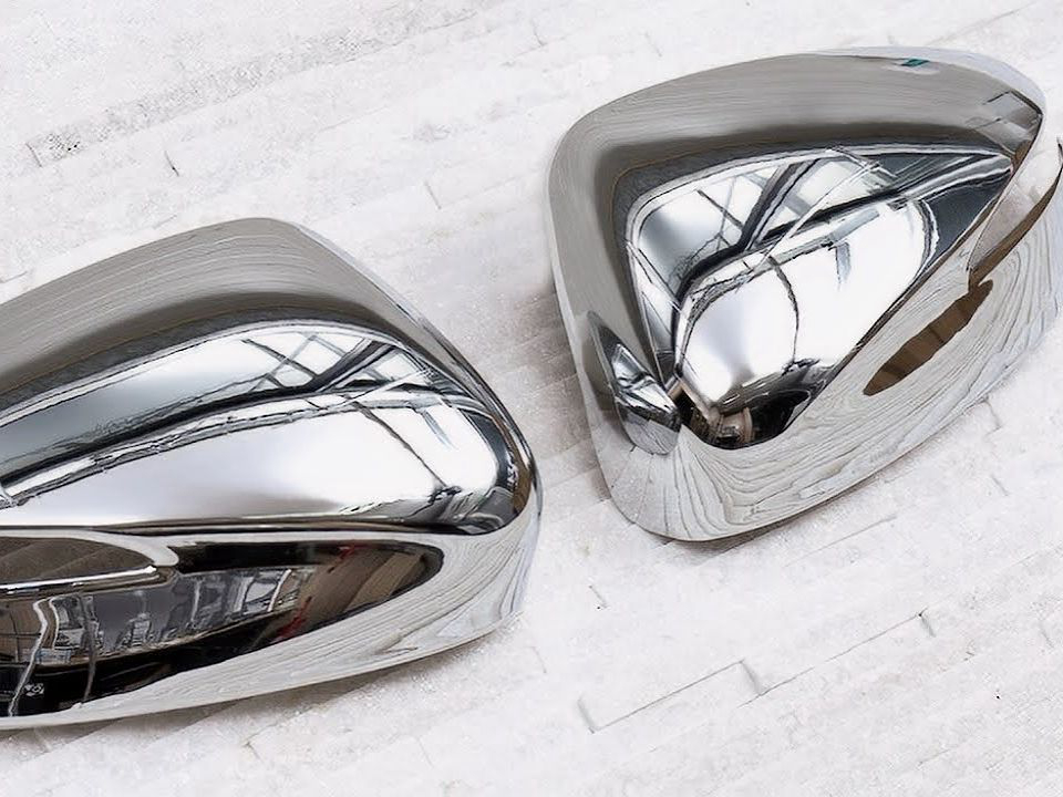
Chrome Plating
learn more
Phosphating
learn more
Nitriding
learn more
Galvanizing
learn more
Lacquer Coating
learn more
Teflon Coating
learn more
Thermal Coatings
learn more
Thermal Barrier Coatings
learn more
Passivation
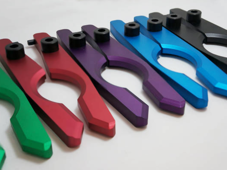
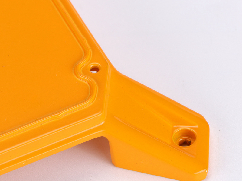
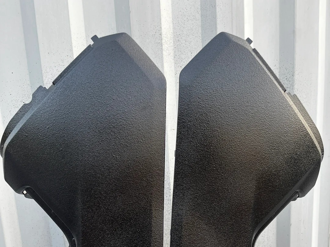
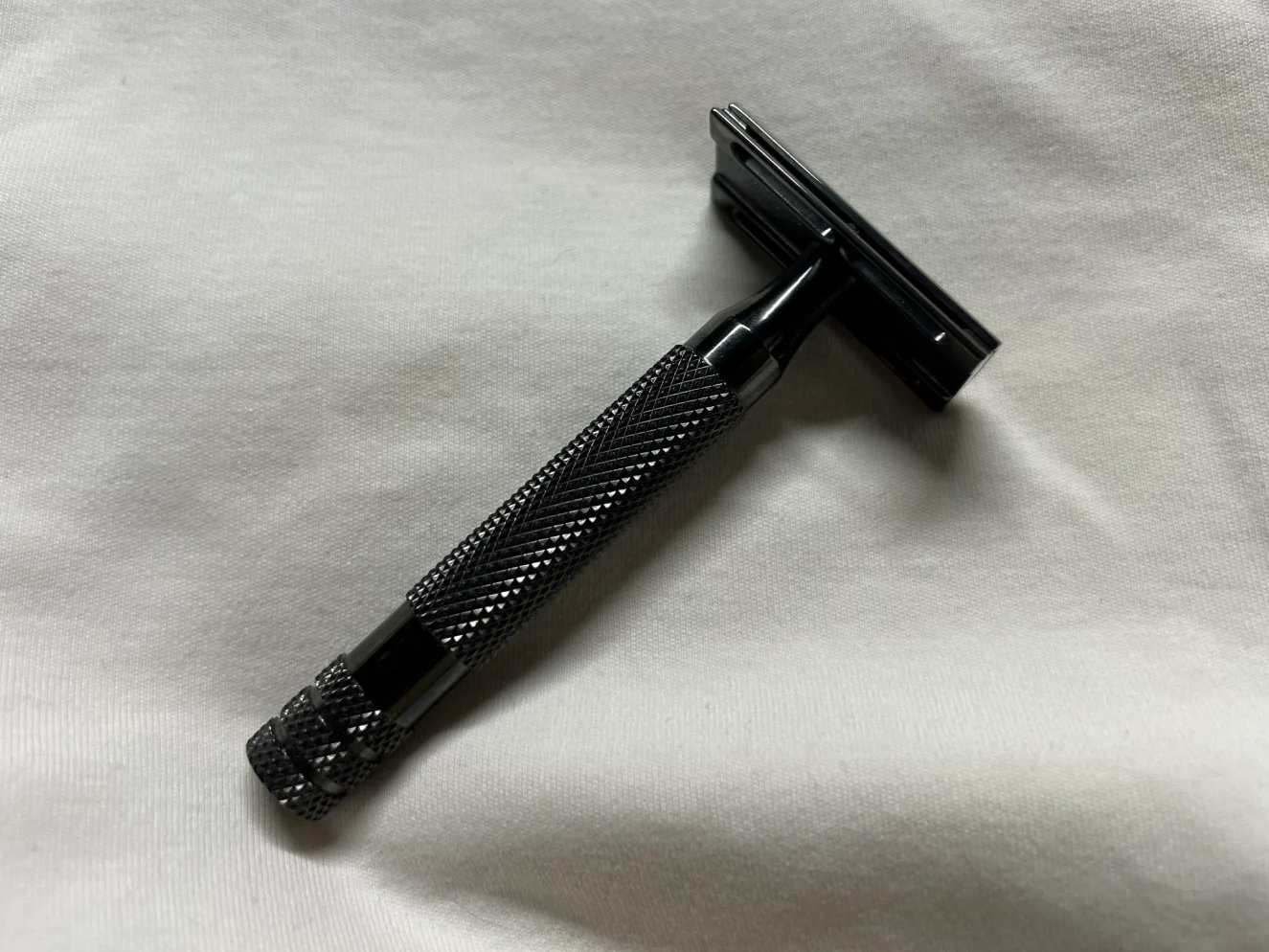
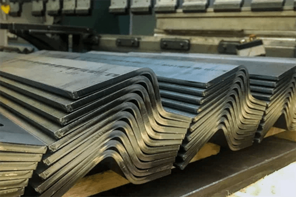
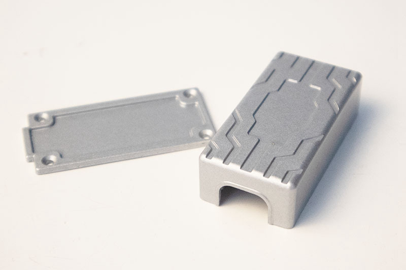
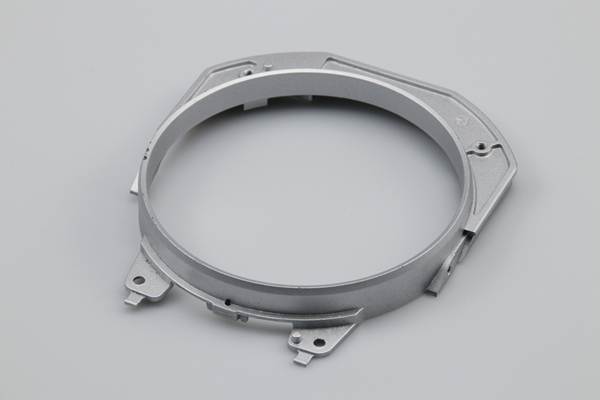
Custom Parts Gallery
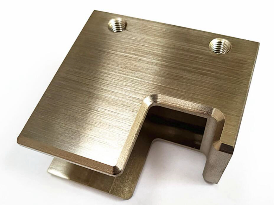
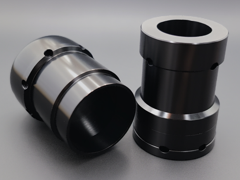
At our custom parts gallery, we understand that every project is unique. That's why we work closely with our customers to ensure that their custom parts are designed to meet their exact specifications. With our attention to detail and commitment to quality, you can trust that your custom parts will exceed your expectations.
Let's Start A New Project Today
Custom Metal Bending Parts Design Guideline
These guidelines present industry standard values for custom metal bending parts. Following these recommendations improves bend accuracy, reduces tool wear, minimizes deformation, and ensures robust, precise, and durable parts for enhanced production quality and cost-effectiveness.
Frequently Asked Questions
Explore Related Resources
Neway Precision Works Ltd.
No.3 Lefushan Industry West Road
Fenggang, Dongguan, China
ZIP 523000
Solutions
Copyright © 2025 Neway Precision Works Ltd.All Rights Reserved.