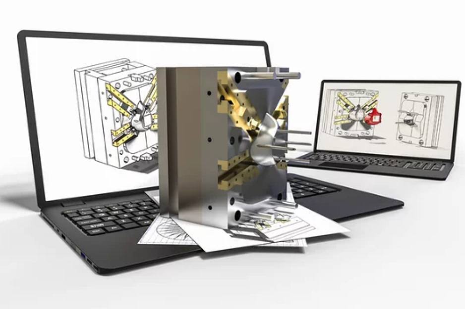
Custom Parts 3D Printing Prototyping Service
Affordable 3D Printing Services for Rapid Prototyping: Need a quick turnaround on your product prototype? Our 3D printing services offer affordable rates without sacrificing quality. Get your product to market in record time.
Send us your designs and specifications for a free quotation
All uploaded files are secure and confidential
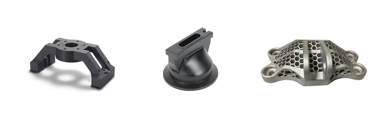
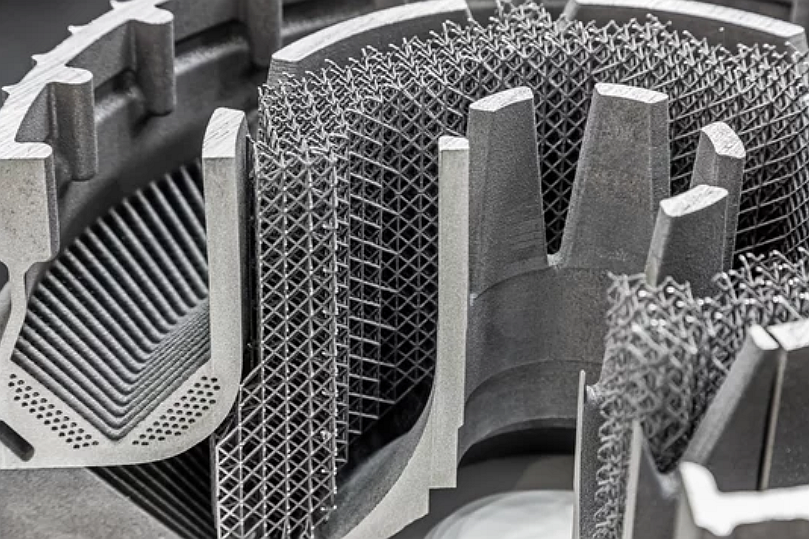
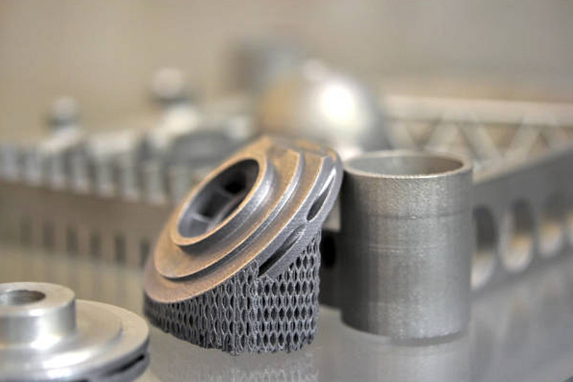
Custom Parts 3D Printing Capabilities and Technologies
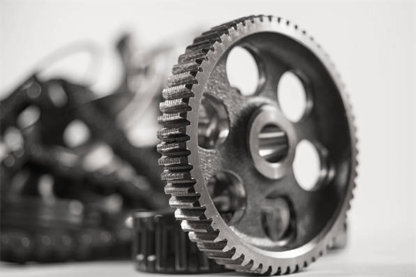
Our Custom Parts 3D Printing Capabilities and Technologies include advanced methods like FDM, SLS, SLA, and DMLS, supporting a wide range of materials. We deliver precise, functional components for diverse industries, tailored to meet specific design and performance requirements.
WAAM, LMD, and EBAM are commonly used to produce durable, high-strength components for industrial and construction applications.
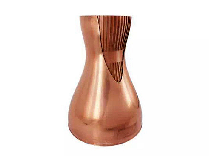
Conductive and heat-resistant parts for electronics and industrial uses; supported by SLM, LMD, and WAAM processes.
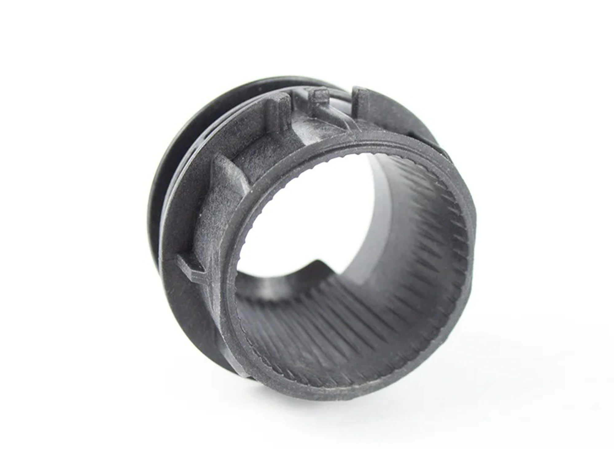
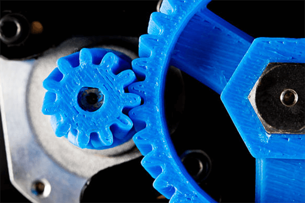
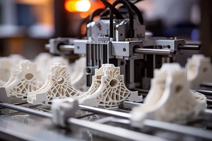
FDM, FFF, SLS, and PolyJet excel in affordable, versatile prototyping and production of lightweight, functional components in various industries.
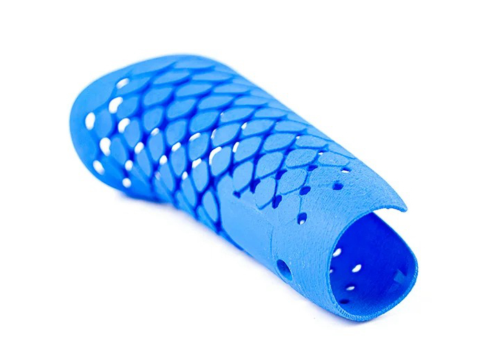
SLA, DLP, and CLIP provide highly detailed, smooth-finish parts for dental, jewelry, and consumer goods with UV-curable liquid resins.

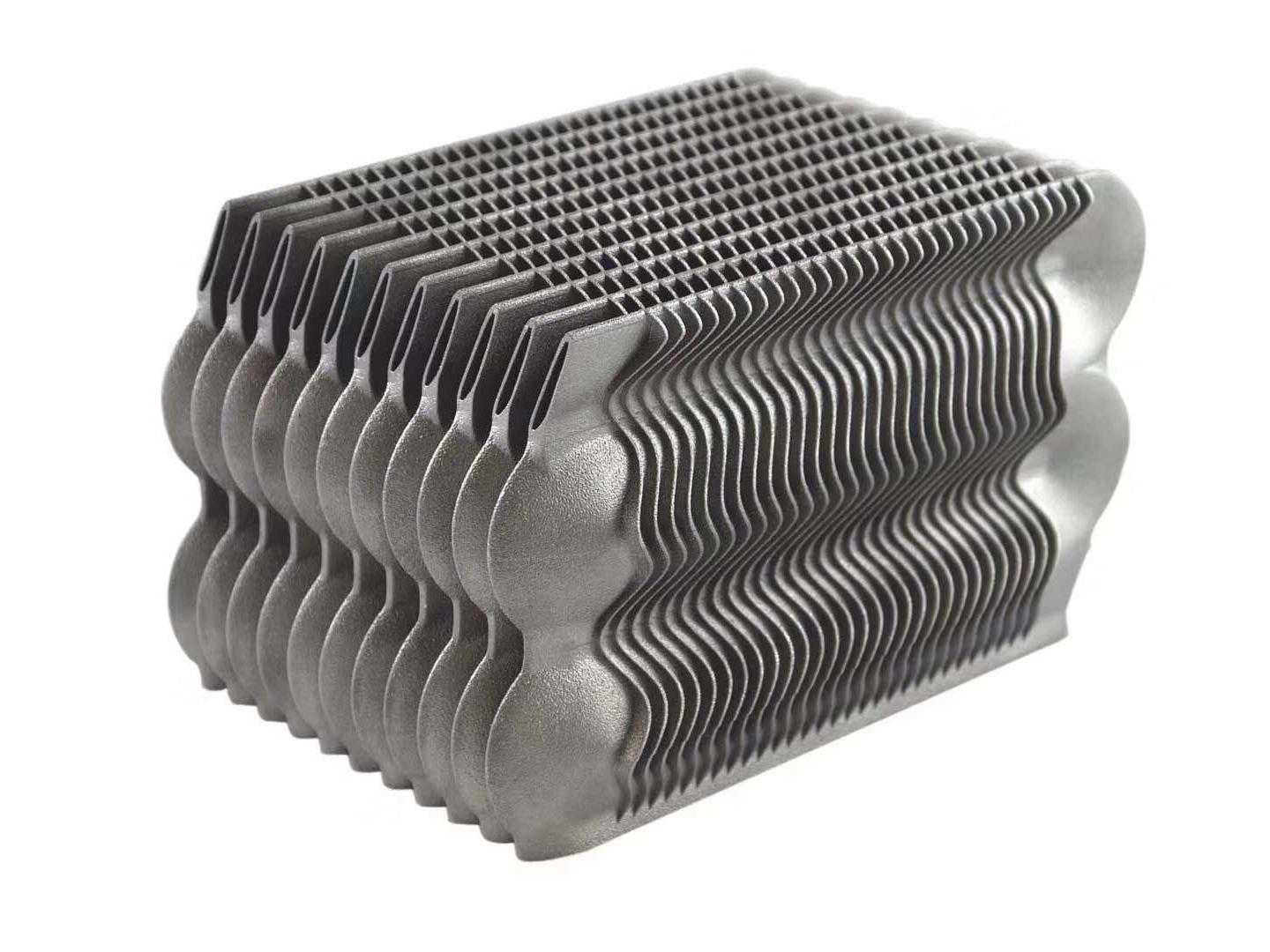
Used in aerospace and energy sectors, processes like SLM, DMLS, and EBAM create strong, heat-resistant parts for extreme environments.
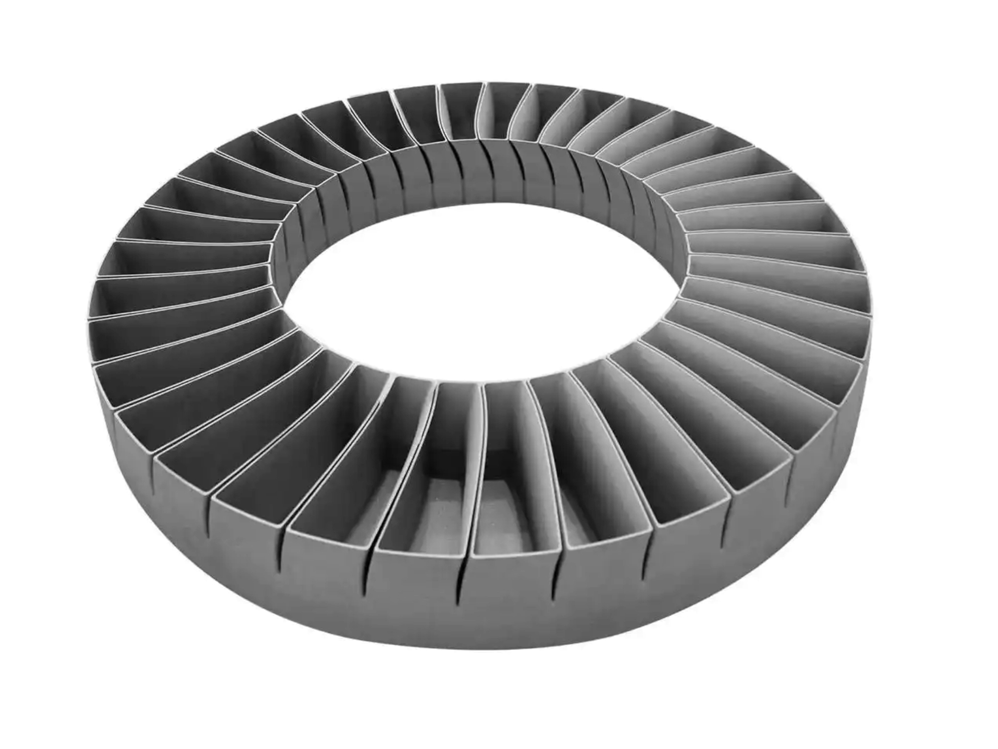
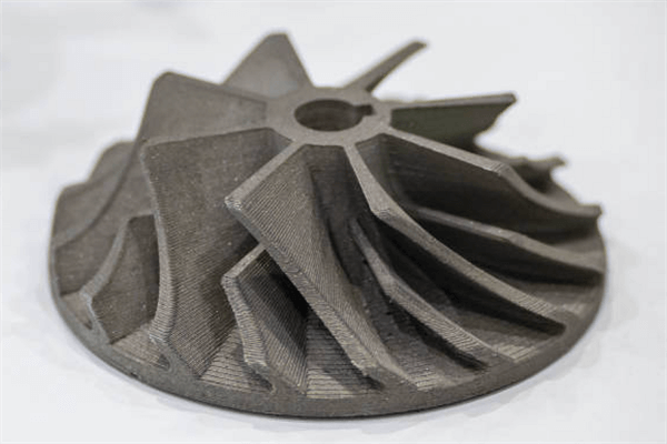
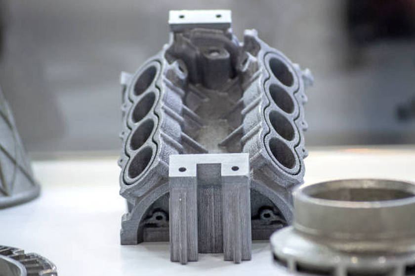
Ideal for aerospace, medical, and automotive industries; SLM, DMLS, and EBM produce lightweight, corrosion-resistant, high-strength components.
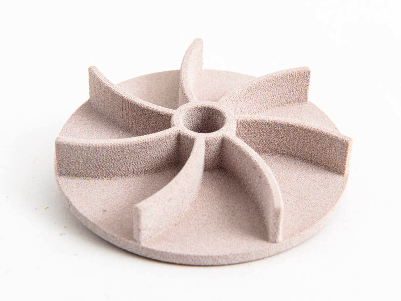
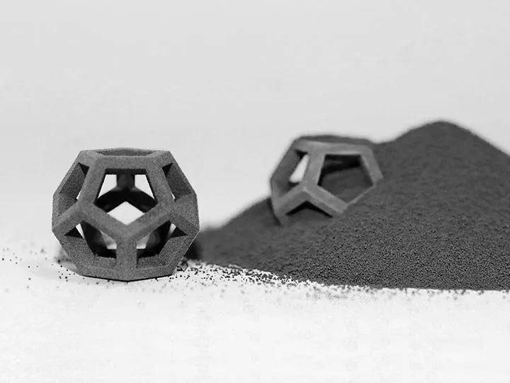
SLS and Binder Jetting create precise, heat-resistant parts for medical, electronics, and industrial applications with excellent durability.
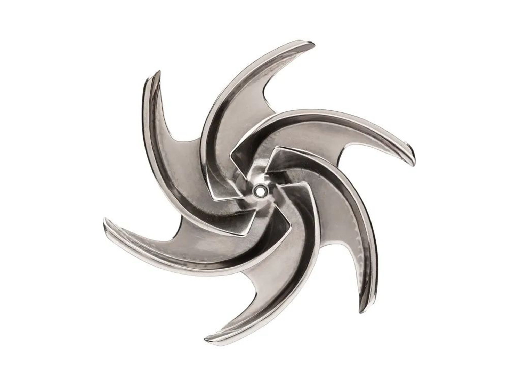
Commonly used in DMLS, SLM, and Binder Jetting for durable, corrosion-resistant parts in engineering, medical, and construction applications.
WAAM, LMD, and EBAM are commonly used to produce durable, high-strength components for industrial and construction applications.
Conductive and heat-resistant parts for electronics and industrial uses; supported by SLM, LMD, and WAAM processes.
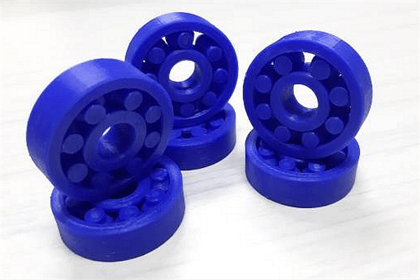
FDM, FFF, SLS, and PolyJet excel in affordable, versatile prototyping and production of lightweight, functional components in various industries.
SLA, DLP, and CLIP provide highly detailed, smooth-finish parts for dental, jewelry, and consumer goods with UV-curable liquid resins.
Used in aerospace and energy sectors, processes like SLM, DMLS, and EBAM create strong, heat-resistant parts for extreme environments.
Ideal for aerospace, medical, and automotive industries; SLM, DMLS, and EBM produce lightweight, corrosion-resistant, high-strength components.
SLS and Binder Jetting create precise, heat-resistant parts for medical, electronics, and industrial applications with excellent durability.
Commonly used in DMLS, SLM, and Binder Jetting for durable, corrosion-resistant parts in engineering, medical, and construction applications.
WAAM, LMD, and EBAM are commonly used to produce durable, high-strength components for industrial and construction applications.
Conductive and heat-resistant parts for electronics and industrial uses; supported by SLM, LMD, and WAAM processes.
FDM, FFF, SLS, and PolyJet excel in affordable, versatile prototyping and production of lightweight, functional components in various industries.
SLA, DLP, and CLIP provide highly detailed, smooth-finish parts for dental, jewelry, and consumer goods with UV-curable liquid resins.
Used in aerospace and energy sectors, processes like SLM, DMLS, and EBAM create strong, heat-resistant parts for extreme environments.
Advantages of 3D Printing Service
Our 3D printing service offers rapid prototyping, complex design capabilities, cost-effectiveness, and customization for advanced manufacturing solutions.
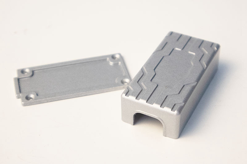
Applications of Custom Printed Parts
Our custom printed parts process offers versatile, on-demand production for prototypes and low-volume manufacturing. Explore a range of custom printed components tailored to various industry needs.

3D Printing Prototyping Materials
Neway 3D Printing Prototyping Capabilities
Prototyping Just Got Easier with 3D Printing: Ditch the messy, time-consuming prototyping methods and switch to 3D printing. Our service offers quick turnaround times and precision accuracy.
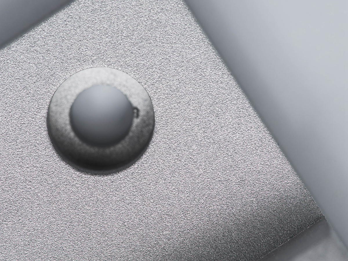
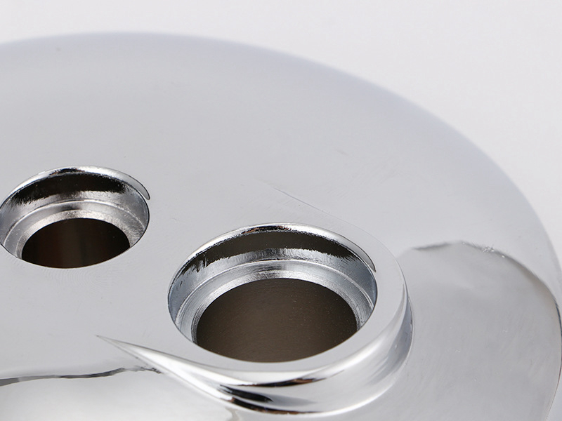
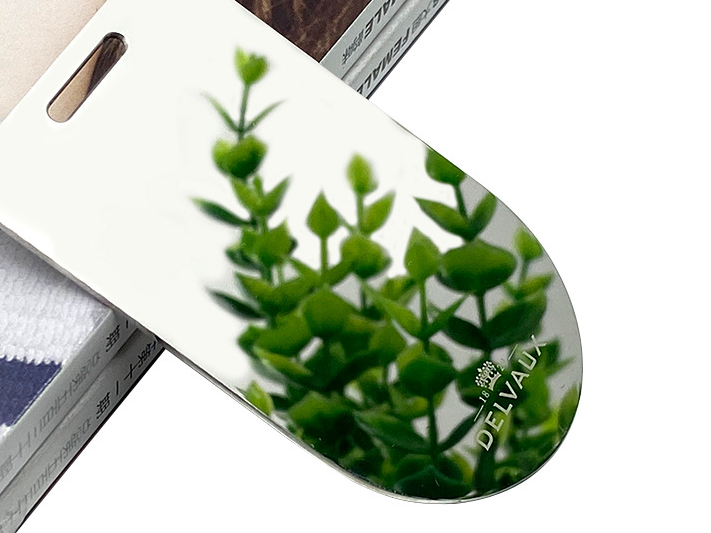
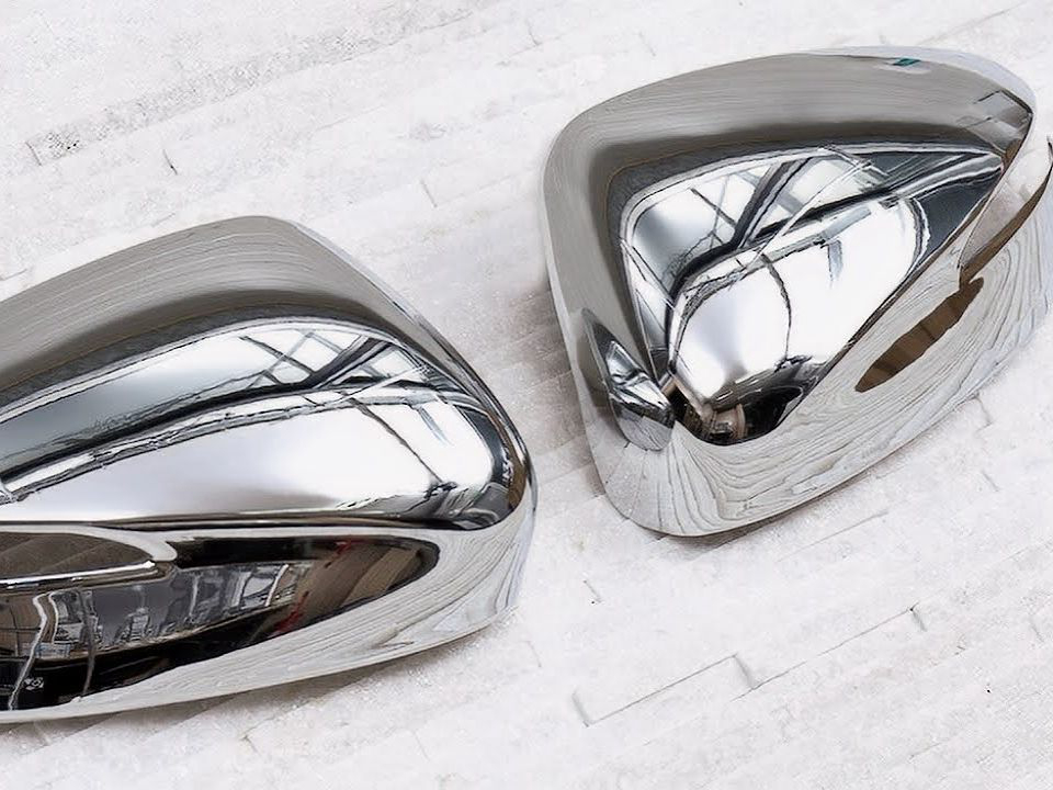
Custom Parts Surface Finishing Available
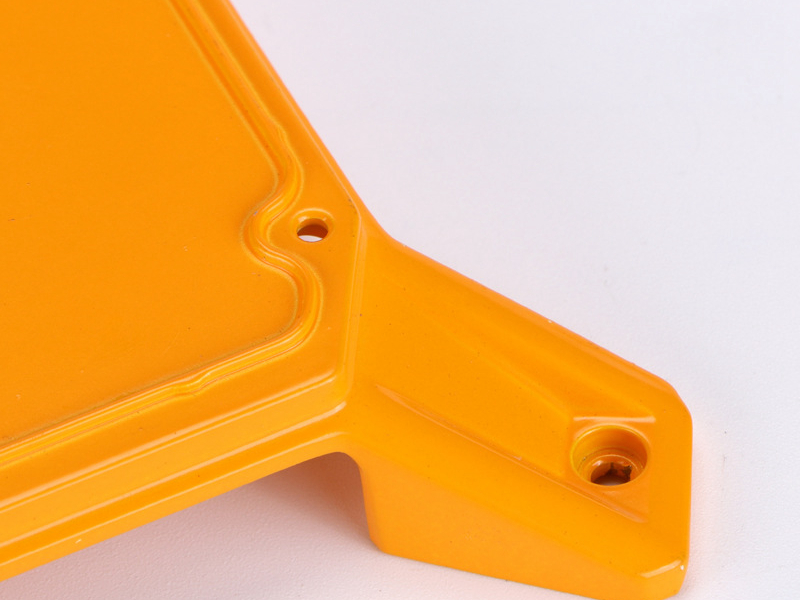
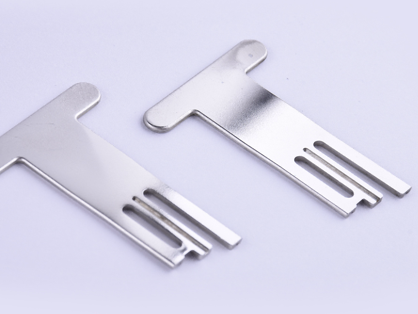
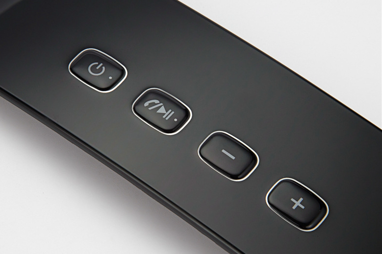
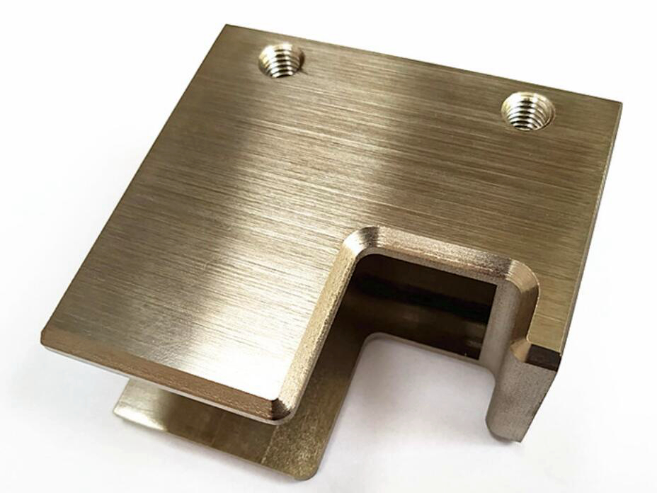
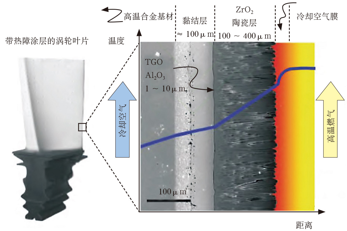
Our Surface Treatment Service offers specialized finishes for custom parts, enhancing durability, aesthetics, and performance. We provide a range of processes, including Electroplating, Anodizing, Powder Coating, and Thermal Barrier Coatings, tailored to improve corrosion resistance, wear properties, and visual appeal of metal and plastic components across industries.
learn more
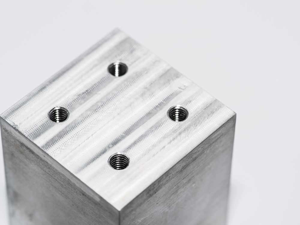
As Machined
learn more
Painting
learn more
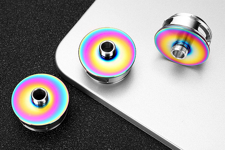
PVD
learn more
Sandblasting
learn more
Electroplating
learn more
Polishing
learn more
Anodizing
learn more
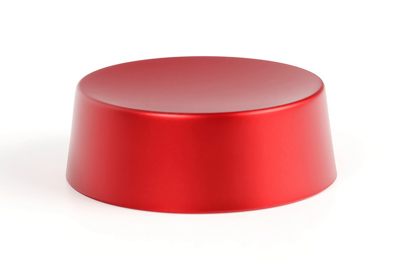
Powder Coating
learn more
Electropolishing
learn more
IMD
learn more
Brushed Finishes
learn more
Black Oxide

learn more
Heat Treatment
learn more
Tumbling
learn more
Alodine
learn more
Chrome Plating
learn more
Phosphating
learn more
Nitriding
learn more
Galvanizing
learn more
Lacquer Coating
learn more
Teflon Coating
learn more
Thermal Coatings
learn more
Thermal Barrier Coatings
learn more
Passivation
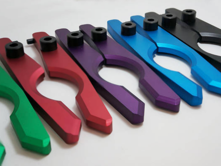
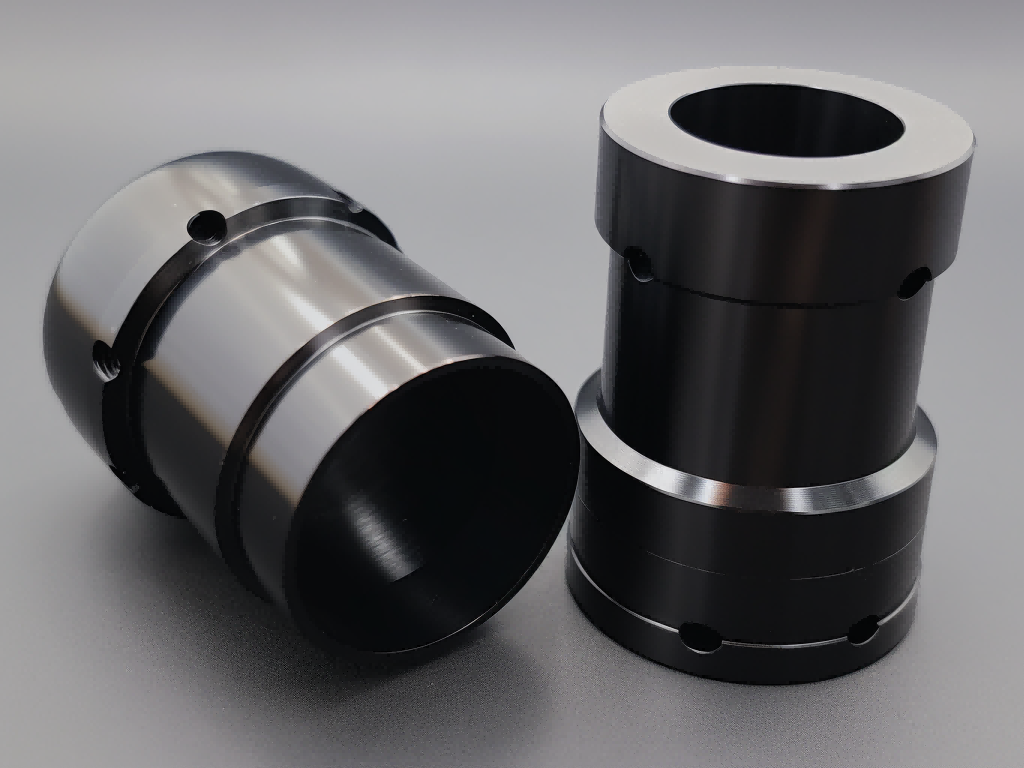
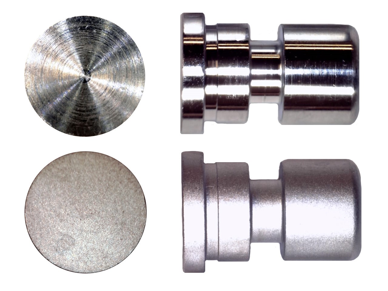
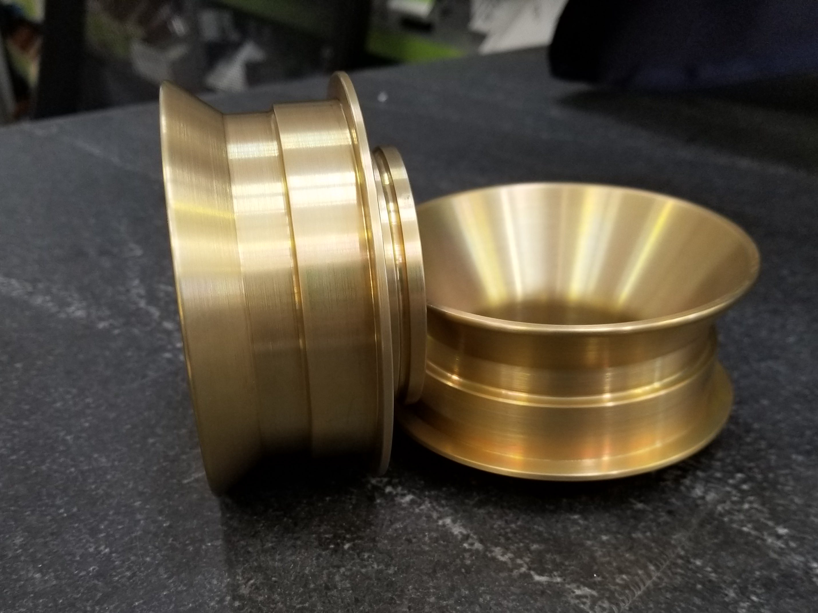
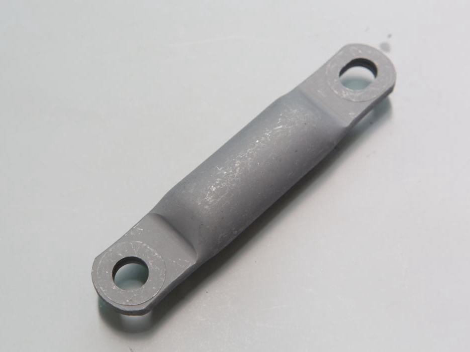
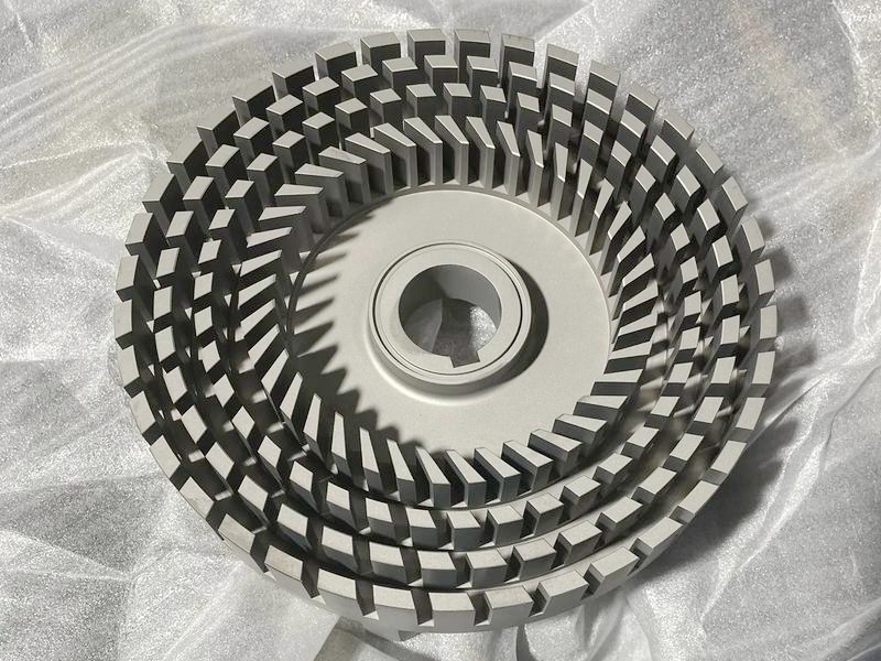
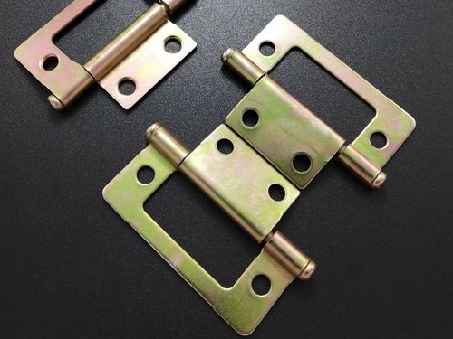
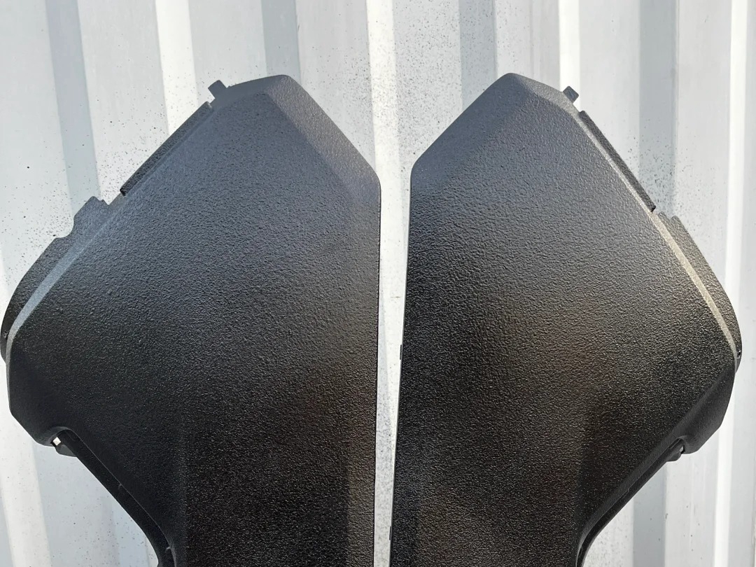
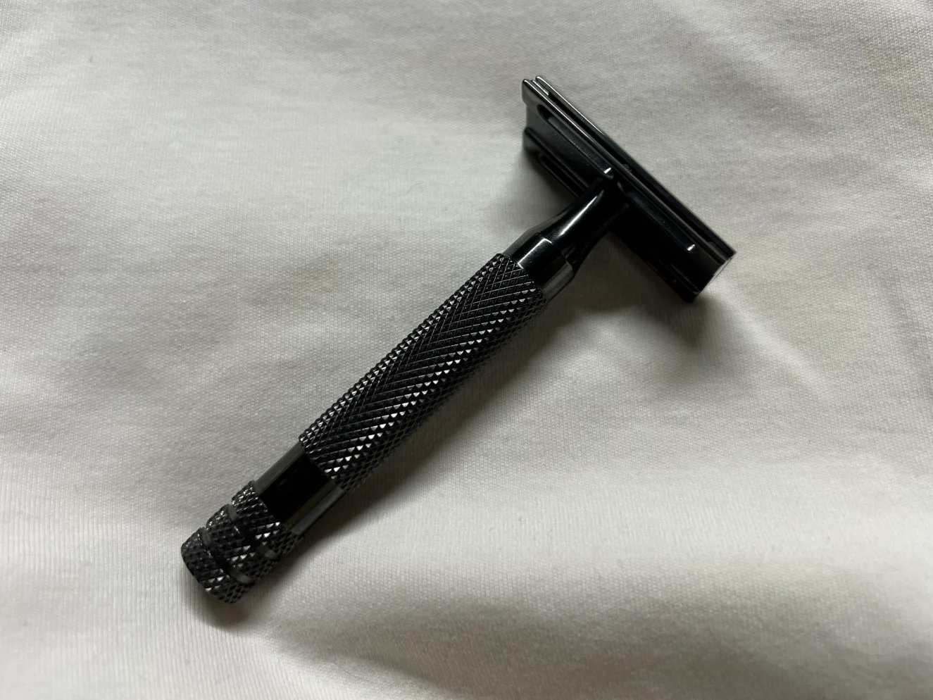
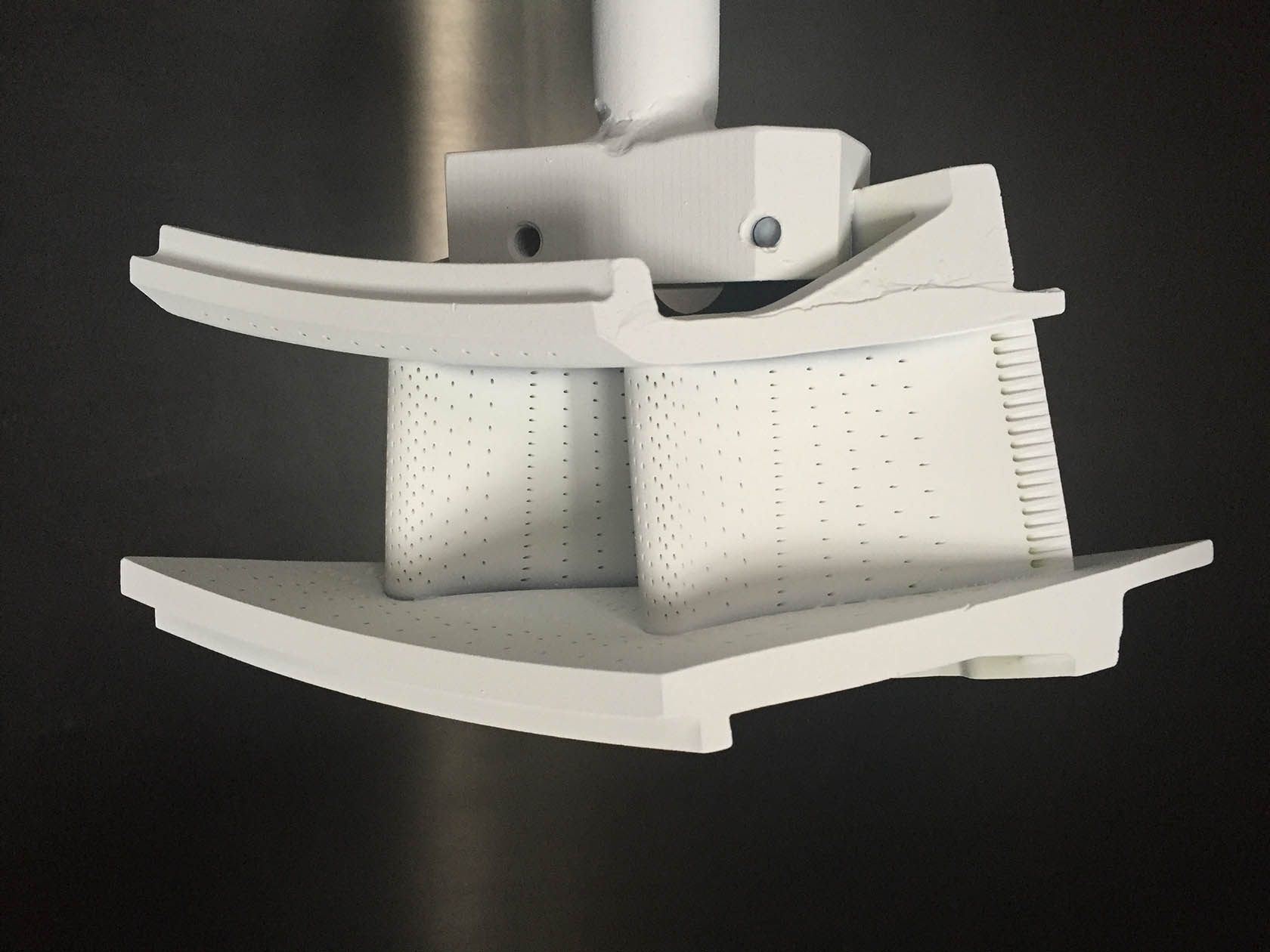
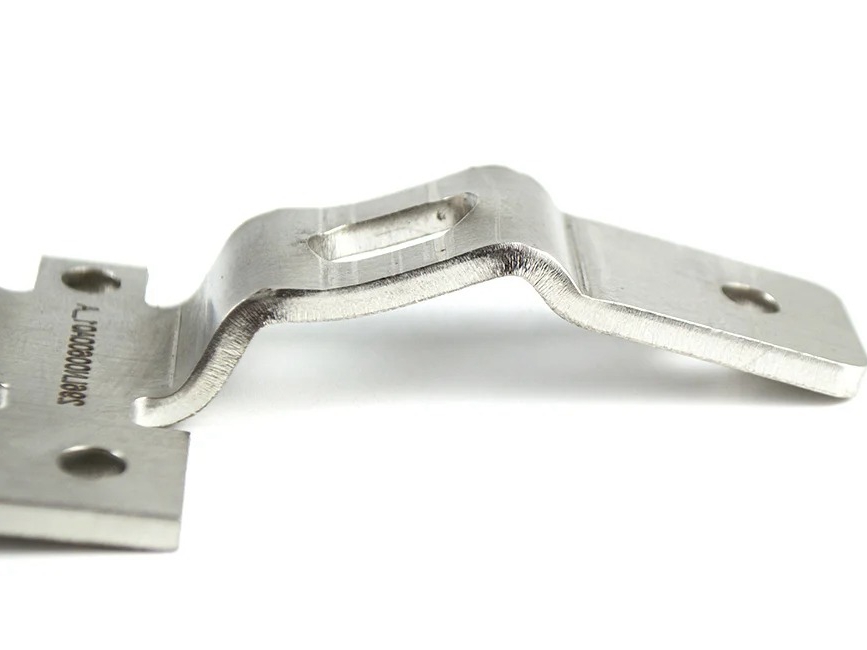
Custom Parts Gallery
At our custom parts gallery, we understand that every project is unique. That's why we work closely with our customers to ensure that their custom parts are designed to meet their exact specifications. With our attention to detail and commitment to quality, you can trust that your custom parts will exceed your expectations.
Let's Start A New Project Today
Custom 3D Printed Parts Design Guideline
These guidelines offer industry standard values for custom 3D printed parts to ensure optimal strength, quality, and production efficiency. They balance precision, print speed, and cost while minimizing defects and post-processing.
Frequently Asked Questions
Explore Related Resources
Neway Precision Works Ltd.
No.3 Lefushan Industry West Road
Fenggang, Dongguan, China
ZIP 523000
Solutions
Copyright © 2025 Neway Precision Works Ltd.All Rights Reserved.